EN
4
4
5
Installation
The device is suitable for surface mounting in any position. It is fastened to a
flat surface using four screws (supplied). The drilling template enclosed de-
fines the position and size of the holes.
On an uneven surface, the unevenness is to be corrected, e.g. using washers.
The electrical connection is made using plug-in screw type terminals.
Ensure that the device is always accessible for operation, testing, inspection,
maintenance or repair.
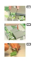
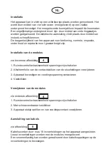
Installation of the modules
See top figure
1. Removing the Room-Controller Basis Device from voltage
2. Removing the protection film for the mating surfaces of the control lines
3. Plug-in of the device and contacting with the input voltage
4. Snapping in
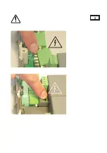
Removing the modules
See bottom figure
1. Removing the Room-Controller Basis Device from voltage
2. Unlocking with a screwdriver
3. Lifting the device slightly and removing from the contacting of the input
voltage.
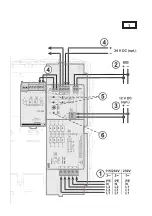
Connection of wires
See figure
Cables enter the device through max. 18 cable entries. Open cable entries are
included with the modules. Strain relief can be provided by using cable ties at
the cable entries.

