Operation Manual / TPL76-C
7 Removal and installation / 7.3 Installing the turbocharger
© Copyright 2017 . All rights reserved.
HZTL2485_EN
Revision E
July 2017
7.3 Installing the turbocharger
u
Remove the cover from the oil connection.
u
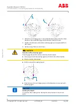
Inspect the lifting gear.
u
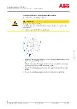
Fasten the lifting gear to the suspension lugs on the bearing casing
and the turbine-end foot.
CAUTION
Oil orifice plates
An orifice plate for adjusting the oil pressure is fitted in each of the two
oil inlet channels in the bearing casing. When the cartridge group, the
bearing casing or the turbocharger is fitted to the engine, it must be
ensured that the orifice plates that are specified for the turbocharger
have been installed in the two oil inlet channels.
u
Check correct installation of oil orifice plates.
u
Fit the turbocharger to the engine.
u
Tighten the fixing screws on the foot.
NOTICE
The fastening specifications for the foot fixing screws are supplied to
the engine builder by ABB Turbo Systems and given in his manual.
u
Fasten the gas, air and oil lines in accordance with the engine
builder’s instructions.
Version with compressor wheel cooling system
u
Fit the air supply line (also see the chapter entitled Preliminary re-
marks / Layout and functioning).
u
Plug in the cable connector on the speed sensor.
Page
79
/
133

