


31
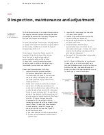
I N SP EC T I O N , M A I N T EN A N C E A N D A DJ US T M EN T
3.
Verify correct operation of the recloser
using the electrical controls.
4.
Perform a hi-pot test to verify the
vacuum integrity.
High voltage applied across an open gap
in a vacuum can produce X-ray radiation.
Radiation note:
When high voltage is applied
across an open gap in a vacuum, X-ray radiation
can be produced. No radiation is emitted when
the recloser is closed because there is no gap.
Additionally, when the recloser is open to the
specified contact spacing during service or testing
within the specified voltages, X-ray radiation at one
meter is below a concerning level. However, there
could be a danger at voltages above or contact
spacing below the specified values on the
nameplate. Follow these steps for the hi-pot test:
a. With the recloser in the open position,
connect the three top terminals and
the three lateral terminals with jumpers.
Ground the lateral terminals and the
housing. Connect the high voltage source
to the top terminals.
b. Stand more than one meter away before
energizing the high voltage source.
c. Do not exceed 37.5 kV for 15/27 kV or 38 kV
reclosers, and do not apply the voltage for
more than 60 seconds.
Do not use DC voltage for hi-pot testing.
Applying DC voltage for hi-pot testing
is more destructive and, therefore, is not
recommended.
d. If internal flashover occurs, isolate the
phases and test each one independently
to identify the defective interrupter.
Replace any defective pole assembly
before putting the recloser into service.
5.
Measure the contact resistance using suitable
equipment (e.g., micro-ohm meter) rated
at least 100 A DC. The resistance should
not exceed 150 micro-ohms. Measure the
resistance across terminals H1 and H2 when
the contacts are closed.
6.
Measure the actuator coil resistance for each
phase. The coil resistance should not exceed
10 ohms. Refer to table 2 for the correct set
of pins to measure the coil resistance.
—
Table 2: Actuator coil resistance measurement pins
24-pin control 32-pin control
42-pin control
Phase A
Pins 10, 22
Pins Y, Z
Pins 2, 3
Phase B
Pins 9, 21
Pins F, G
Pins 4, 5
Phase C
Pins 8, 20
Pins H, J
Pins 6, 7
7.
Measure the microswitch resistance for the
52a/b contacts. This can be done at the pole
level, on the other end of the control cable
or inside the control cabinet terminal block.
This measurement can also verify continuity.
The measured resistance should not exceed
1.5 ohms. Refer to table 3 to identify the
correct set of pins for measuring microswitch
resistance.
—
Table 3: Microswitch resistance measurement pins
24-pin
control
(52b)
32-pin
control
(52a)
42-pin
control
(52a)
42-pin
control
(52b)
Phase A
Pins 7, 19
Pins F, U
Pins 29, 9
Pins 29, 22
Phase B
Pins 7, 6
Pins F, V
Pins 29, 8
Pins 29, 17
Phase C
Pins 7, 18
Pins F, W
Pins 29, 1
Pins 29, 16
Note: For 24-pin (52b) and 42-pin (52b) measurements,
the recloser needs to be in the open state.
8.
Perform a battery test (if programmed).
Press the PROG1 button on the front of the
RER620. The RER620 will display a “Delta V”
voltage. This value should not exceed 10
percent of the nominal battery voltage (e.g.,
4.8 V for a 48 V battery). A returned value of
99 V for the “Delta V” indicates that the
battery has a very low charge, is disconnected
or has failed. The Delta indication will also
provide a “Pass” or “Fail” message.
For reclosers using the ACM control cabinet,
the battery is continuously monitored by the
Nextys UPS, eliminating the need for periodic
battery testing. If a battery problem arises during
continuous monitoring, an alarm is activated
in the relay.
09
Содержание GridShield 3P
Страница 1: ... DISTRIBUTION SOLUTIONS GridShield 3P 3SP recloser Installation operations and maintenance manual ...
Страница 2: ......
Страница 4: ... GridShield 3P 3SP recloser ...
Страница 27: ...27 INSTALL ATION 8 2 2 Substation mount recloser grounding 36 GridShield 3P substation mount grounding 36 0 8 ...
Страница 39: ...IMPORTANT SAFET Y NOTES AND WARNINGS 39 ...