2TLC172015M0201, rev. D
Original instructions
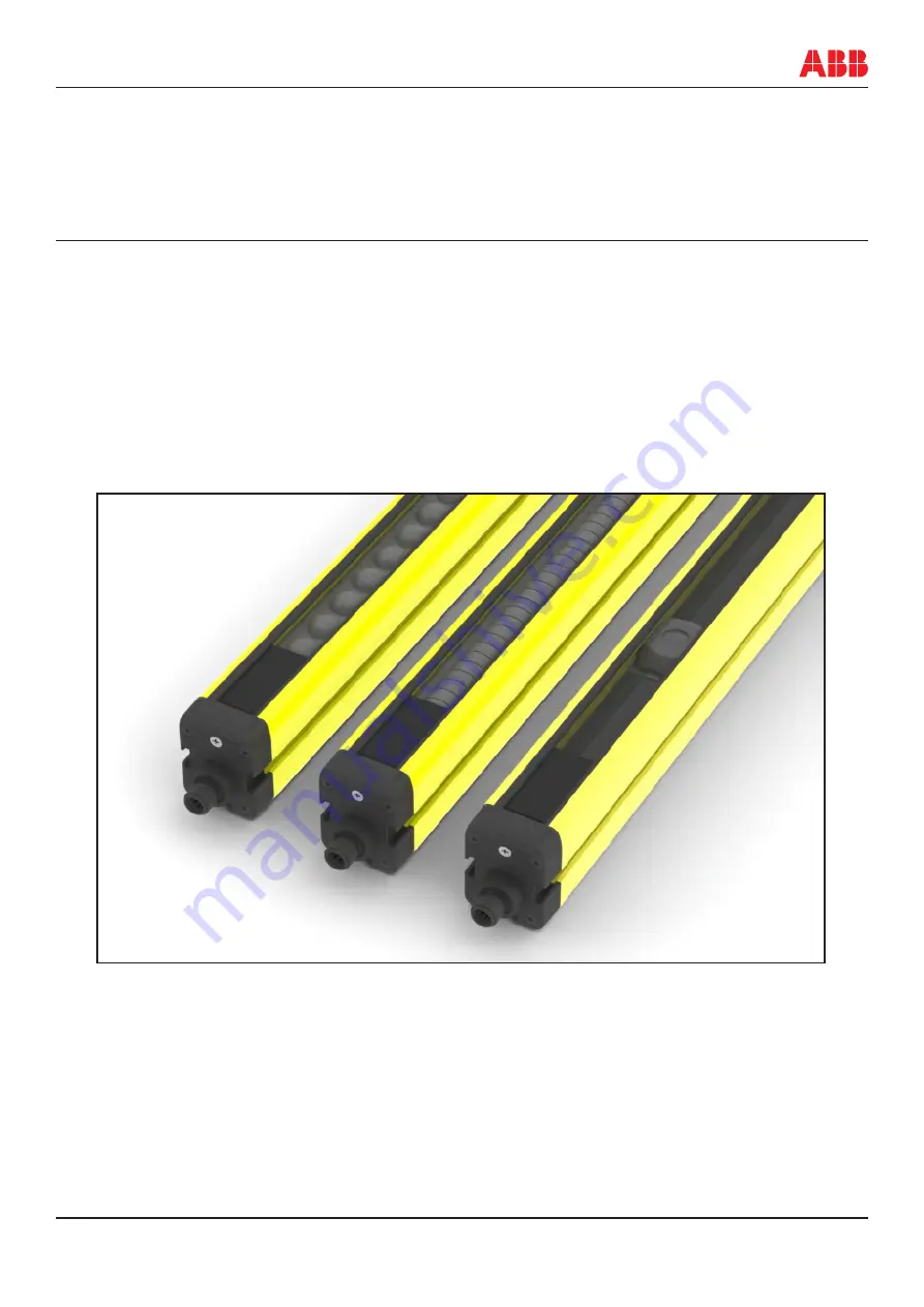
Focus II
Light grid / Light curtain
Active optoelectronic protective device (AOPD) Focus II Type 4
ABB AB JOKAB SAFETY
Varlabergsvägen 11, SE-434 39, Sweden
www.abb.com/lowvoltage
Страница 1: ...15M0201 rev D Original instructions Focus II Light grid Light curtain Active optoelectronic protective device AOPD Focus II Type 4 ABB AB JOKAB SAFETY Varlabergsvägen 11 SE 434 39 Sweden www abb com lowvoltage ...
Страница 2: ...JOKAB SAFETY will provide applicable third party certification documents identi fying ratings and limitations of use that apply to the products This information by itself is not sufficient for a complete determination of the suitability of the products in combination with the end product machine system or other application or use The following are some examples of applications for which particular...
Страница 3: ... in M12 C01 C04 Connectors 16 4 3 Setting up of Internal Change Over Switches Transmitter 17 4 4 Setting up of Internal Change Over Switches Receiver 18 4 5 Setting up Scan Codes 20 4 6 Choice of Reset Procedure 20 5 Connection Examples 21 5 1 Connection Example Basic with and without muting 21 5 2 Connection Example for connection to safety relay 22 5 3 Connection Example muting unit to safety re...
Страница 4: ... function 40 10 2 Double Break function 40 11 External Device Monitoring EDM 41 12 Checkout Procedure 42 13 Transmitter LED Information 43 14 Receiver LED Information 44 15 Regular checkout and test 46 16 Technical specifications 47 17 Accessories cables 49 18 Wet enclosure 50 19 Bjorn stands 51 20 Dimensions of brackets and profile 53 21 Dimensions of MFII mirrors and bracket 54 22 Variant list a...
Страница 5: ...0 1200 800 500 900 1200 800 500 Range m SR LR 0 2 3 3 6 0 2 7 7 14 0 5 20 20 40 0 5 20 20 40 0 5 20 20 40 0 5 20 20 40 0 5 20 20 40 0 5 20 20 40 0 5 7 0 5 8 0 5 12 Reaction time off ms See 5 7 See 5 7 13 13 13 13 13 13 13 13 13 Reaction time on ms See 5 7 See 5 7 142 142 142 142 142 142 142 142 142 Manual reset Automatic reset Pre reset Muting inputs Muting lamp supervision Override Muting T L X B...
Страница 6: ...se operational disturbance Do not use woollen cloth solvent or any other material when cleaning which may scratch or in some way damage the surface of the cover Operational conditions decide how often the cover needs to be cleaned ABB AB JOKAB SAFETY does not accept any liability for damage or injury due to incorrect use of the protection barriers or associated components 1 3 Important information...
Страница 7: ... not occur such as by configuring series connections or using physical barriers between adjacent sets 2 Function and Possibilities Short Description A beam of infra red light is generated and sent from transmitter to receiver If anyone should interrupt this beam the OSSD outputs of the safety barriers see 5 1 are opened and brings hazardous functions in machinery to a safe state Safety barriers co...
Страница 8: ...am is correct LED 1 2 3 and 5 are lit to indicate this D Override see 7 Only and always possible when a muting indicator LMS is connected If the button is pressed after 2 s but within 5 s after voltage has been switched on and is then pressed for at least 5 s the OSSD outputs of the light curtain will be activated only if any beam is interrupted If the entire protective field is free for more than...
Страница 9: ... profile slots see 17 19 22 These make it easier to adjust the transmitter and receiver in level with each other NB If several barriers are used they must be mounted so that each transmitter does not interfere with the receiver of a nearby barrier Multiple barriers should be installed as below or could be used with coding see 4 5 and 5 6 The scan code feature of the Focus II system allows for plac...
Страница 10: ...oth ways to find the outermost positions return the transmitter to the midpoint The barrier is correctly aligned when the LED 3 is constantly lit even if one of the profiles is somewhat turned After aligning the barrier secure the screws firmly Disconnect the power supply Restore the barrier s power supply with the test reset contact closed If the safety area is clear and automatic reset is chosen...
Страница 11: ...other protective measures step b and c are not necessary a SRT K T CRT K approach speed of body parts towards hazardous area 2000 mm s shall be used if S is equal to or less than 500 mm Min value of S 100 mm NB If FII 4 30 is used in single double break mode min value of S 150 mm 1600 mm s can be used if S is greater than 500 mm Min value of S 500 mm T Overall system stopping performance1 T1 T2 wh...
Страница 12: ...0 0 1600 1150 1150 1100 1000 900 850 750 450 0 0 0 0 1400 1200 1200 1100 1000 900 850 650 0 0 0 0 0 1200 1200 1200 1100 1000 850 800 0 0 0 0 0 0 1000 1200 1150 1050 950 750 700 0 0 0 0 0 0 800 1150 1050 950 800 500 450 0 0 0 0 0 0 600 1050 950 750 550 0 0 0 0 0 0 0 0 400 900 700 0 0 0 0 0 0 0 0 0 0 200 600 0 0 0 0 0 0 0 0 0 0 0 0 0 0 0 0 0 0 0 0 0 0 0 0 When a value of zero is given the calculatio...
Страница 13: ... stopping performance T1 T2 where T1 reaction time of light curtain s T2 stopping time of machine including reaction time of control system s C 1200 0 4 H Shall not be less than 850 mm H 15 d 50 Minimum allowed height of detection zone above reference plane mm NB Shall not be less than 0 or greater than 1000 d resolution mm 14 mm for FII 4 14 and 30 mm for FII 4 30 S minimum distance in mm H the o...
Страница 14: ...f reflection from reflecting surfaces is minimized The minimum distance to a reflecting surface is shown below R EAA EAA d Operating range R is the effective working range of the Focus II system from the transmitter to the receiver EAA is the effective aperture angle of the Safety Sensor It is 2 5 for FII 4 distance d is the minimum distance to a reflective surface This distance must be greater th...
Страница 15: ... to work The indicator should be placed so that it is visible from all sides with access to the hazardous area of the machine See connection example in 5 and text in 6 The OSSD outputs of the barrier are PNP outputs which are each current limited to 500 mA If the cur rent will exceed 500 mA or if alternating current is to be connected the system may benefit from being connected to a safety relay s...
Страница 16: ... M12 C03 for connection to receiver Male 5 pin connector M12 C02 1 2 5 4 3 1 2 5 4 3 8 1 7 6 5 4 3 2 3 7 5 4 6 8 2 1 4 2 Connection of Cable C5 C8 in M12 C01 C04 Connectors Female 5 pin connector M12 C01 for connection to transmitter NB It is recommended to use ABB AB JOKAB SAFETY standard M12 cables whenever possible See 18 for a list of cables and accessories Seen from the cable connection side ...
Страница 17: ...NB Make sure to always set switches in both banks to the same position Switch position Setting Function 1 OFF Range setting X ON Short range 2 OFF Range setting X ON Long range 3 OFF Code setting No coding ON Coding 4 OFF Code setting Code A ON Code B Selector switches 5 8 are not used in the transmitter Switch 1 Switch 2 Range selected OFF OFF Not allowed OFF ON Long range ON OFF Short range ON O...
Страница 18: ...anking 1 beam with T muting OFF OFF ON Muting on module 1 2 3 and 4 Blanking 1 0 beam with T muting OFF ON OFF Muting on module 1 2 and 3 Blanking 0 beam with T muting OFF ON ON Muting on module 1 and 2 Blanking 1 beam with L muting ON OFF OFF Muting on module 1 Blanking 1 0 beam with L muting ON OFF ON Muting on module 2 Blanking 0 beam with L muting ON ON OFF Muting on module 3 Pre Reset mode ON...
Страница 19: ... time difference of approx 30 ms is mandatory 6 Refers to max muting time 600 s but not to the time between A and B 120 s NB For further information about T L and X muting see 6 1 6 5 Light grid specific settings Muting maps when muting T L or X are selected on switches 4 and 5 3 Special functions selection when switches 4 and 5 are both ON 4 3 2 1 1 2 3 OFF OFF OFF Muting all beams Muting T with ...
Страница 20: ...l length of the cable between the transmitter and receiver required when coding is used see 5 6 does not exceed 100 m 4 6 Choice of Reset Procedure Reset of Focus II barrier may be reached in three different ways A Automatic reset The barrier is reset directly after the protection area has become clear Change over switch No 8 is set in position On see 4 4 B Manual reset The barrier is reset when t...
Страница 21: ... aligning and overriding with the muting function used see 2 NB If test reset button is not used the white conductor must be connected to 24VDC Without muting With muting 1 2 3 4 5 Brown 24VDC Blue 0V Brown 24VDC Blue 0V 1 2 3 4 5 6 7 8 White Test Reset Green Yellow Muting A Muting B NC for X muting OSSD 1 RL 500mA max OSSD 2 RL 500mA max Muting Lamp 220Ω 3W Grey Pink Red Screen Ground Screen Grou...
Страница 22: ...en Switch 8 must be set to OFF If test reset is also connected it may be used for other functions see 2 The LMS indicator L1 signals opened barrier or safety relay NB If test reset is not connected the white wire must be connected to 24VDC If test reset and are pressed and are released at the same time no reset occurs NB The connections in the drawing above which are marked with bold lines should ...
Страница 23: ... S34 S13 S14 S23 S53 Y13 Reset X1 X4 S13 Type RT9 A1 A2 ABB S14 S34 S44 S24 Y14 Test Auto Reset X1 X4 C D B B A A White Black Grey 2 2 1 2 3 4 5 1 2 3 4 5 6 7 8 1 2 3 4 5 1 2 3 4 5 6 7 8 Transmitter Receiver Muting unit Muting unit M12 Cable L1 FMC 1 Tina FMC 2 Tina Tina 10A Tina 10B Tina 10C 24VDC 0V L1 1 2 3 4 5 Brown 24VDC Blue 0V Brown Blue 1 2 3 4 5 6 7 8 White Green Yellow Grey Pink Red Scre...
Страница 24: ...e Type Pluto 24V 0V ABB I1 I0 Q0 Q1 Brown Blue 1 2 3 4 5 6 7 8 White Green Yellow Grey Pink Red Screen Receiver 24VDC 0V Test Reset Muting A Muting B OSSD 1 RL 500mA max OSSD 2 RL 500mA max Muting Lamp 220Ω 3W Ground C D B A A B C D 1 2 3 4 5 Brown 24VDC Blue 0V Brown 24VDC Blue 0V 1 2 3 4 5 6 7 8 White Test Reset Green Yellow OSSD 1 RL 500mA max OSSD 2 RL 500mA max Grey Pink Red Screen Ground Scr...
Страница 25: ...000 1703 1631 1617 65 75 50 100 231 7 33 FII 4 14 1800 2TLA022201R1000 1851 1778 1764 65 80 53 97 252 7 36 FII 4 14 1950 2TLA022201R2000 1998 1925 1911 65 86 57 93 273 7 39 FII 4 14 2100 2TLA022201R3000 2145 2072 2058 65 92 61 93 294 7 42 FII 4 14 2250 2TLA022201R4000 2292 2219 2205 65 97 64 98 315 7 45 FII 4 14 2400 2TLA022201R5000 2439 2366 2352 65 103 68 104 336 7 48 FII 4 30 150 2TLA022201R600...
Страница 26: ...50 13 142 2 4 2 1 FII 4 K2C 900 2TLA022205R0000 1098 300 912 150 13 142 2 4 2 1 FII 4 K2C 1200 2TLA022205R1000 1398 400 1212 150 13 141 2 4 2 1 Weight of Focus II Light curtains FII 4 yy 150 300 450 600 750 900 1050 1200 1350 1500 1650 1800 1950 2100 2250 2400 Kg 0 83 1 39 1 95 2 51 3 07 3 63 4 19 4 75 5 31 5 87 6 43 7 0 7 55 8 11 8 67 9 24 Weight of Focus II Light grids FII 4 Ky 500 800 900 1200 ...
Страница 27: ...on Protection SW release Prod date Serial no Operating temp RoHS Certified by TÜV CSA ABB AB JOKAB SAFETY Varlabergsvägen 11 434 39 Kungsbacka SWEDEN Jokab Safety A F L G H B I C J D E K M Bar code A Model type e g FRII 4 14 600 FII Focus II receiver transmitter FRII Focus II receiver FTII Focus II transmitter B Power supply 24 VDC C Power consumption e g 5 W D Protection IP65 E Software release e...
Страница 28: ...e muting function is activated if the OSSD outputs are active and muting input A then is closed while muting input B is opened Either sensor can be activated ahead of the other or both at the same time The muting function remain as long as the terms are met indicator working A and B activated See 5 If the muting function is possible and something happens to the muting indicator e g a lamp breakage...
Страница 29: ...sensor B X muting Either A och B can be activated first 2 Additional settings timings available for Focus II light grids see 4 4 3 The maximum time that Focus II will allow muting A or muting B to drop without detecting a muting stop Features Muting grid Bypassing of light curtain or grid in one or two directions L form T form Connected directly via a M12 cable to light curtain grid Muting type Se...
Страница 30: ...t must be as short as possib le Timing limitations and the speed of the material transport must be considered additionally d3 is the distance between the two sensors connected to Muting A input This distance represents the minimum length of the material to be detected Timing requirements and limitations If Muting A is activated Muting B must be activated within 120 s to activate the muting functio...
Страница 31: ...ust be considered additionally d is the distance between the Focus II system and the sensor connected to Muting A input This distance represents the minimum length of the material to be detected Timing requirements and limitations If Muting A is activated Muting B must be activated within 120 s to activate the muting function Otherwise muting function is not achived Muting A and Muting B cannot be...
Страница 32: ...inputs Muting A must be a sensor with high output NO and Muting B must be a sensor with low output NC when the sensor is interrupted i e an object is detected Timing requirements and limitations Either Muting A or Muting B can be used to initiate the muting function The second muting sensor must be activated within 4 s of the first sensor to activate the muting function Muting A and Muting B can b...
Страница 33: ...to disconnect two or more modules or even the whole barrier NB When muting a single module the module that contains the synchronising optical beam which is located furthest away from the M12 connector must not be chosen If it is the muting func tion is disabled If muting is chosen from a module which does not exist e g muting of the 4th module in a barrier that only has 3 modules e g FII 4 K3 800 ...
Страница 34: ...be blocked If the entire protective field is free for more than 2 s the override function is immediately stopped A Test request on the TEST RESET input will stop the override function immediately Maximum timeout for override is 600 s After this timeout the Focus II system is restarting according to the interlock mode set by the selector switches At start up Switch off the power supply Restore the ...
Страница 35: ...be selected using pre reset function Muting function can not be selected using pre reset function The time limit between pre reset and manual reset is 8 s Pre reset setup and connection example Enable pre reset mode with the internal change over switches See 4 4 Connect a pre reset button to MUTING A input green and 24 VDC to MUTING B input yellow Pre reset sequence 1 Press pre reset button LED 5 ...
Страница 36: ...ple blanked areas of different sizes Setting of Blanking is done by a teach in or with BP 1 see 9 1 When blanking is used the blanked area must be continuously and entirely occupied by material fixtures fixed guards or removable interlocking guards Example using additional mechanical guarding Where 1 part that permanently blocks 3 beams eg a support table 2 area that needs additional mechanical gu...
Страница 37: ...in accordance with EN ISO 13855 using the resolution given in the table above see 3 3 Clearly mark the new resolution on all labels 4 pcs of the Focus II system after setting the blanking mode with a permanent marker pen as shown on picture below Name Tolerance Resolution mm FII 4 14 yyyy FII 4 30 yyyy Blanking 1 Pattern 1 beam 28 60 Blanking 1 Pattern 1 beam 21 45 Blanking 0 Pattern 14 30 Origina...
Страница 38: ...NG B inputs from 24 VDC 9 The barrier works normally and signals blanking operation by the flashing of the LED 2 To Turn Blanking Off Blanking mode is deactivated with the internal change over switches See 4 4 NB Programming of blanking with no object in the optical field does NOT deactivate blanking The tolerance setting and the new resolution are still present Blanking Programmer BP 1 Facilitate...
Страница 39: ...rotective field will result in an interlock situation A manual restart is necessary to start the single double break function sequence again after power on or any other interruption of the protective field while the machine is working Input from restart and or feedback must be longer than 300 ms Minimum time of interrupting the protective field is 300 ms Load unload must be completed within 30 s a...
Страница 40: ...er run state and machine operates While the machine is in operation the feedback is not tested When end position is reached the feedback input provide a high to low transition Safety outputs enter stop state 10 2 Double Break function This operation mode is similar to single break operation except Operator is doing a loading and an unloading cycle manually Focus II system will enter the run state ...
Страница 41: ...for a closed to 24VDC condition If this is found it will enter a state consistent with the selected operating mode When the Focus II system enables its safety outputs it monitors the external devices for a closed to open transition This transition must occur within 300 ms or the Focus II system will then enter an alarm state Additionally if the EDM connections are incorrectly wired the system will...
Страница 42: ...e tooling change set up adjustment or modification to the Focus II system or the guarded machine Where a guarded machine is used by multiple operators or shifts it is suggested that the test procedure is performed at each shift or operator change Testing ensures that the light curtain and the machine control system work properly to stop the machine Failure to test properly could result in serious ...
Страница 43: ...selected Error conditions LED indication Name of LED Colour 1 Green 2 Yellow 3 Green 4 Not used Red 5 Yellow 1 2 3 4 5 Description of error Corrective action 1 Low voltage Check power supply 24 VDC 20 2 º º Control logic fault Check that change over switch bank 1 and bank 2 are equal Remove and reapply power If error is still present contact your local ABB AB JOKAB SAFETY distributor 3 º Error on ...
Страница 44: ... reset 7 º Pre reset button pushed Waiting for reset 1 flash sec Blanking 8 º Floating blanking active 9 º Floating blanking active object in protective field Single double break 10 º Waiting for manual restart of single double break function sequence after power on or after interruption of the protective field while the machine is working 2 flashes sec 11 º Normal operation of single double break...
Страница 45: ...ts Check wiring of the OSSD outputs 4 º º º Muting lamp connection fault or defective Check the connection of the muting lamp and or check condition of the muting lamp 5 º Mutual light interference Check the presence of ambient light sources close to the protection field Use coding option or remove the light source 6 º º Error in floating blanking mode Object not present Check the position of the ...
Страница 46: ...system remain in the OFF state and the red LED 4 is lit during the entire test and yellow LED 5 is lit when test tool is removed Automatic reset The outputs of the Focus II system remain in the OFF state and the red LED 4 is lit during the entire test 2 Activate the TEST RESET 2 5 s Check that the safety outputs of the Focus II system become volta ge free The red LED 4 is lit and the machinery is ...
Страница 47: ...2 for distances 3 m Response time ON to OFF Maximum 103 ms See 5 7 for more information Light source Infrared Emitting LEDs Wavelength 880 nm Power Dissipation 3 mW Class 1 acc EN60825 1 Mechanical Housing material Painted aluminium yellow RAL 1018 Front plastic material Polycarbonate Connector material Polyamide 6 6 End cap material Polyamide 6 6 Sealing gasket material EPDM Mounting bracket mate...
Страница 48: ...ith IEC60742 and be able to cover a drop of supply voltage of at least 20 ms Protection class IEC 536 or VDE 106 III Power on delay 2 s Insulation resistance 20 MΩ Dielectric voltage strength 350 VAC 1 min Connections Cable length Focus II Shielded cables Max 100 m 0 4 mm Max 50 m 0 2 mm Cable length Focus II CUT Shielded cables M12 connector 8 pin these cables are shipped with the sensors Maximum...
Страница 49: ...12 female connector M12 C203 2TLA020056R4100 20 m cable 8x0 34 mm with straight M12 female connector M12 C134 2TLA020056R5000 1 m cable 8x0 34 mm with straight M12 female male M12 C334 2TLA020056R5100 3 m cable 8x0 34 mm with straight M12 female male M12 C03 2TLA020055R1600 8 pin connector female with screw connection M12 C04 2TLA020055R1700 8 pin connector male with screw connection C8 2TLA020057...
Страница 50: ...e possibility for drainage or aeration in order to avoid condensation A Focus II with WET need to be assembled by the ABB Jokab Safety factory When ordering specify cable length out from the WET tubes and aslo specify operation mode internal change over switches see 4 4 Length incl lid Barrier 54 mm Total length Barrier 154 mm Material tube PC Material lid PE Max operating temperature 55 C ...
Страница 51: ...t can be easily reached The base has radius slotted holes and centre marks to ease the stand orthogonal positioning N2 14 kg H2 V2 15 kg N3 17 kg H3 N4 1 18 kg H4 1 20 kg N4 2 22 kg H4 2 24 kg N5 27 kg Mirror reduction 10 Material thickness Metal sheet 3mm Painting Epoxy Ral 1018 H2 V2 and N2 are stock items Ø 231 145 180 230 190 15 4 3 131 90 146 100 110 500 353 1000 253 400 400 1230 243 300 300 ...
Страница 52: ...Standard FII 4 K1C 500 and mirror in Bjorn N2 stands to FII 4 K1C 500 with Bjorn V2 mirror stand 238 131 40 742 1000 218 940 1230 218 1025 1330 218 1325 1599 218 1770 2050 12m 24m Bjorn N2 2TLA022041R4500 Bjorn N3 2TLA022041R4600 Bjorn N4 1 2TLA022041R4700 Bjorn N4 2 2TLA022041R4800 Bjorn N5 2TLA022041R4900 ...
Страница 53: ...23 25 5 39 Ø 6 5 Ø 18 1 0 12 13 28 5 0 7 20 5 25 5 39 46 46 35 2 5 22 30 18 50 37 48 16 70 Ø 18 Profile Article No Description 1 2TLA022090R0100 Mounting bolt 2 2TLA022090R1000 JSM 66 3 2TLA022090R2400 Plastic washer 4 2TLA022090R0400 Washer 5 2TLA022090R0200 Lock nut JSM 66 2TLA022090R1000 Mounting bolt 1 3 2 4 5 ...
Страница 54: ...MFII 750 2TLA022041R0500 801 MFII 900 2TLA022041R0700 958 MFII 1050 2TLA022041R1200 1108 MFII 1200 2TLA022041R0800 1258 MFII 1350 2TLA022041R1300 1408 MFII 1500 2TLA022041R0900 1551 MFII 1650 2TLA022041R1000 1708 Bracket for MFII mirrors Article no 2TLA022041R2000 2 pieces for each mirror JSM 70 2TLA040001R1500 Plate for easy adjustment on uneven floors 40 40 35 15 Ø 8 5 0 20 60 75 Ø 20 40 20 15 M...
Страница 55: ...3 4 5 24V supply to transmitter Muting lamp total 3 5W Led panel On In A In B Muting OSSD1 OSSD2 Muting sensor A activated Muting sensor B activated Led flashing Led on Safety output 1 High Safety output 2 High Muting activated Muting lamp fault Alt 1 1 3 Supply to transmitter Muting lamp FMI 1 Alt 2 Alt 3 Sensor B1 Sensor B2 Sensor A2 Sensor A1 M12 3B M12 3B M12 3B Receiver B M12 3B Receiver A M1...
Страница 56: ...elay outputs and power supply JS SP 1 protection plug for not used connectors JS AP 1 adaptor for FMC units to use instead of FMI 1B or 1D on the R connector including muting resistor Muting Lamp Reset Power Off Reset M12 8 M12 5 8 8 8 8 5 8 5 5 5 5 M12 8 8 M12 8 8 5 5 5 5 5 Reset Power Off 8 5 5 1 3 2 1 3 2 1 3 2 Reset 5 Reset Power Off M R B A M R B A M R B1 A1 B2 A2 M R B1 A1 B2 A2 PWR OFF RESE...
Страница 57: ...I system detection zone and the hazardous area Verify that the reset button is only reachable from the safe area and that there is full view of the hazardous area Pass Fail Determine that all access to the hazardous area not protected by the Focus II system is guarded by fence or other fixed guard Pass Fail Inspect the electrical installation between the machine control system and the Focus II sys...
Страница 58: ... the Focus II system installation the cables and wiring If something are damaged secure the machine and report Pass Fail Interrupt the Focus II system detection zone with the supplied test tool See 16 Pass Fail Start the machine Check that the machine stops when the test tool is inserted to the detection zone and it is not possible to restart when the test tool is in the detection zone Pass Fail V...
Страница 59: ... Light curtain ESPE Focus II FII 4 14 30 zzzz Z10 12 09 49833 012 Light beam ESPE Focus II FII 4 K4 zzzz Focus II FII 4 K3 800 Focus II FII 4 K2 500 Focus II FII 4 K4 zzzz D Focus II FII 4 K3 800 D Focus II FII 4 K2 500 D Focus II FII 4 K2C zzzz Focus II FII 4 K2C 800 Focus II FII 4 K1C 500 Z10 12 09 49833 013 Notified body TÜV Süd Produkt Service GmbH Ridlerstrasse 65 80349 München Germany Notifi...
Страница 60: ...ABB AB JOKAB SAFETY 46 0 21 32 50 00 www abb com lowvoltage e mail info jokabsafety se abb com AFBN0043 d ...