Commissioning and service field (ISF)
OI/PME/LME/EAN823/EBN853/EBN861-EN
31
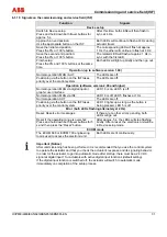
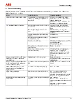
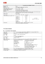
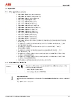
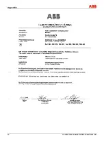
6.1.10 Signals on the commissioning and service field (ISF)
Function
Signals
Device setup
Switch to Device setup:
Press and hold down both travel buttons for
approx. 5 s.
After this time, both LEDs will then flash in
sync at 4 Hz.
Approach an end position:
Use the appropriate button on the ISF.
Both LEDs will continue to flash at 4 Hz during
actuator travel.
Save the initial end position:
Press the 0% or 100% button.
The corresponding LED will flash at approx.
1 Hz, the other will continue to flash at 4 Hz.
Save the second end position:
Press the 0% or 100% button.
The related LED will flash at approx. 1 Hz in
sync with the first LED.
Finish setup:
Press the 0% and 100% buttons at the same
time.
Both LEDs will light up briefly and then go out.
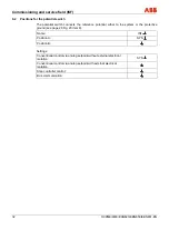
Operation (up to software version 1.60)
Normal operation: MAN / AUT.
The LEDs are off.
Positioning via the button on the ISF takes
priority over the control system.
The LEDs are off.
Operation (software version 2.00 and higher)
Normal operation: MAN via digital input or
graphic user interface.
LED 10 is on, LED 5 is off.
Normal operation: MAN via ISF.
LED 10 is off, LED 5 flashes at 1 Hz.
Normal operation: AUT.
The LEDs are off.
Positioning via the button on the ISF takes
priority over the control system.
LED 10 lights up as long as the button is
being pressed, LED 5 is off.
Error (both LEDs flashing alternately at 4 Hz)
Reset: Resets error messages.
If there are no other errors pending, both
LEDs will go out.
Reset if the operating range is overshot:
Press and hold down both travel buttons for 5
s and then press the “Reset” button.
After approx. 5 s, the LEDs will stop flashing
briefly. After a reset, the electronic unit will be
in Device setup mode.
ECOM mode
The ECOM 688 or ECOM 700 engineering
tool is used to access the electronic unit.
Both LEDs are lit continuously.
Important (Notice)
After commissioning has been performed, it is recommended that you use the control system
to operate the actuator and that you check the actuator's response and its signaling behavior.
In order for the actuator to go into automatic mode after startup, there must be a 24 V DC
signal at digital input 1 for actuators with active digital input functions (default setting).
If the digital input function is switched off, the actuator will switch to automatic mode
immediately on completion of the setup process.

