Chapter
3
-Functional Description
3 - 4
DCS 500 12-Pulse Planning and Start-Up
Current feed-
back, Slave-
Master
Slave:
This transmits the actual current CONV-CUR-ACT (see block dia-
gram for the basic software)
The actual current feedback is read out from SETTINGS, Signal
10501, and passed to Terminal X4:8 (IOB-1) over Pointer 205 from
analog output AO2. The signal is bipolar, but this is not processed
further. Here, too, the master is informed of the polarity using the
signal at X18:9.
Master:
The actual current feedback from the slave is inputted at Terminal
X3:8 of the analog input AI2 (IOB-1). From here, it is passed using
Parameter 10107 to Pointer 3604 at the 12-PULSE LOGIC function
block for further processing.
The master is informed of the signal’s polarity through X18:13.
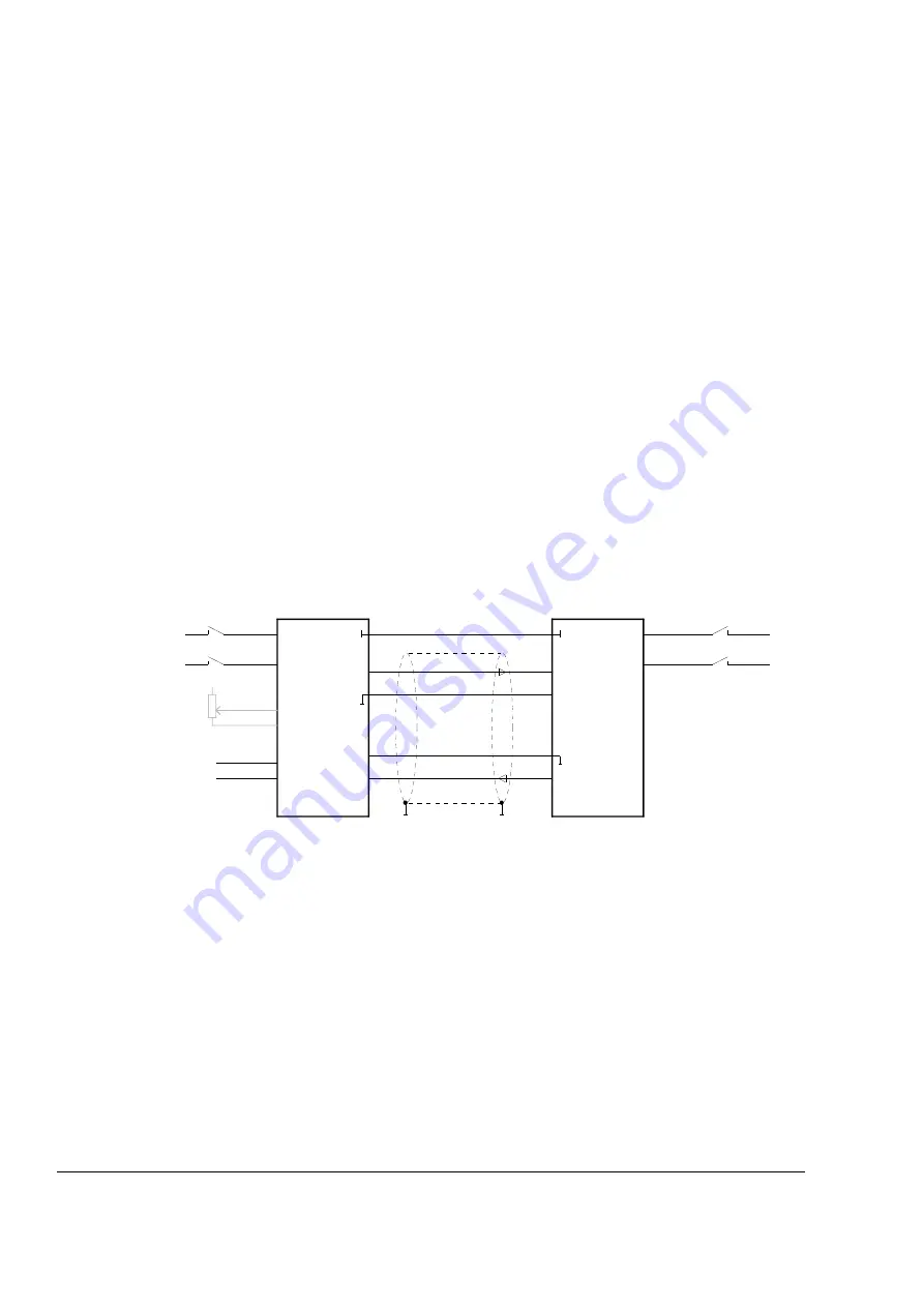
Terminals X4:8 (Slave) and X3:8 (Master) must be connected to
each other using a cable of >1 mm².
To produce the reference potential, Terminal X3:7 must be con-
nected to X4:6 of the two power converters (Master and Slave) us-
ing a cable of >1 mm² (see illustration below).
DCS 500
DCS 500
SDCS-IOB-1
SDCS-IOB-1
X3:4
X3:1
X3:5
X3:6
X6:8
X6:7
X4:8
X18:
X18:
X3:8
X4:8
X6:7
X6:8
X3:8
speed
feedback
reference
RUN
ON/OFF
+/-10 V
Unit 1
MASTER
Unit 2
SLAVE
RUN
ON/OFF
X4:6
X3:7
X4:6
X3:7
Current feedback
Current reference
(analogue)
(analogue)
(digital)
The described “connections” in the software structure are executed
by carrying out the instruction detailed in
Chapter 6 “Start-Up”.
This also contains a proposal for the switch-on/switch-off
logic, which can be customízed by the user to suit his/her own
requirements.


