
Page 13
© 2023 ABB. All rights reserved.
CC1600SC55_QSG
Rev 4.0
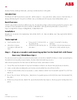
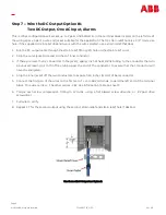
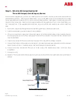
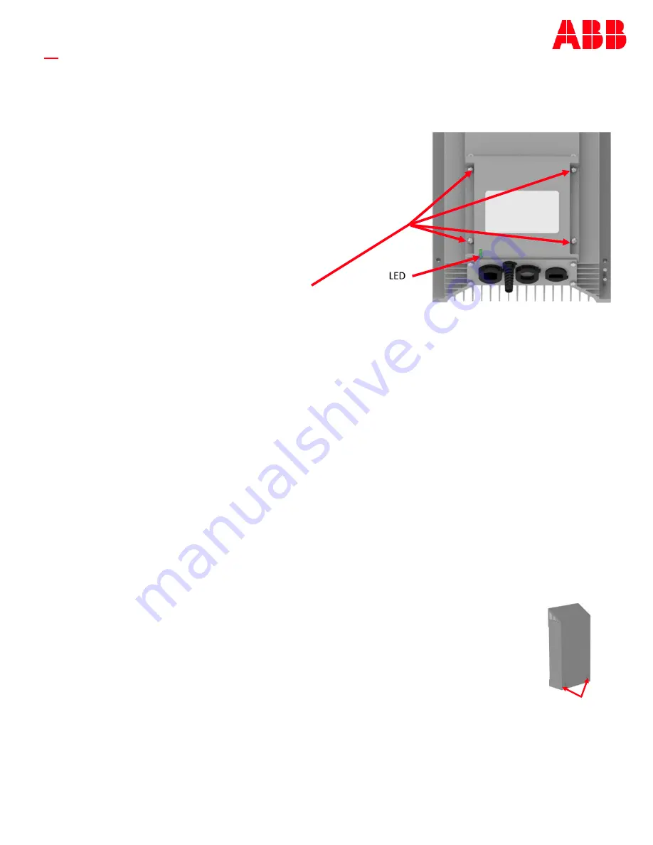
Step 11B
1.
Inspect to see that the separation between the AC and DC compartments is clear of wires from the circuit
card all the way to the bottom cover.
2.
Orient the cover with the LED showing in the
lower left corner when viewed from the front.
3.
Gently push the cover on until each of the tails of
the captive screws is captured in the pilot holes.
4.
Hand tighten the 4 captive screws, making sure
there is no undue force as would be encountered
if a wire were crossing from the AC
compartment the DC compartment underneath
the cover.
5.
Torque each of the 4 captive screws to 13 in
-
lbs.
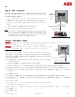
Step 12 –
Apply AC Power and Confirm
-
48V Power Delivery
1.
Terminate, insulate or protect the far end of the DC cables, as these will be energized when AC is applied.
2.
Return to the AC panel feeding the unit.
3.
Unlock the panel.
4.
Energize the panel. (120Vac = 1200W max capacity; 240Vac = 1600W max capacity. 15A or 20A circuit
protection is required.)
5.
Turn on the circuit breaker feeding the Small Cell
-
48V Power Source.
6.
Observe the LED illuminates green, indicating that DC is present on the output terminations.
7.
Confirm that DC is present on the outputs by observing a signal from the radio(s).
8.
Test the alarm contacts by cycling the AC to off. Observe that both alarms are active when no AC is present.
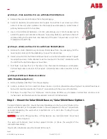
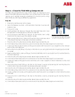
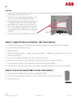
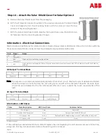
Step 13 –
Attach the Solar Shield Cover for Solar Option 1
1.
Assemble the Solar Shield Cover to the Base, enclosing the rectifier.
2.
Secure the Solar Shield Cover using the two captive screws toward the lower edge of the unit.
3.
Torque to 26 in
-
lbs.
captive screws


