


89
5
INSTALLATION…
f
o
e
p
y
T
-
o
m
r
e
h
T
e
l
p
u
o
c
e
l
b
a
C
g
n
i
t
a
s
n
e
p
m
o
C
3
4
8
1
S
B
1
.
6
9
C
M
I
S
N
A
4
1
7
3
4
N
I
D
0
3
.
o
N
t
r
a
P
7
3
9
4
S
B
+
–
e
s
a
C
+
–
e
s
a
C
+
–
e
s
a
C
+
–
e
s
a
C
l
A
-
i
N
/
r
C
-
i
N
)
K
(
n
w
o
r
B
e
u
l
B
d
e
R
w
o
ll
e
Y
d
e
R
w
o
ll
e
Y
d
e
R
n
e
e
r
G
n
e
e
r
G
n
e
e
r
G
e
t
i
h
W
*
n
e
e
r
G
li
s
i
N
/
li
s
i
r
c
i
N
)
N
(
e
g
n
a
r
O
e
u
l
B
e
g
n
a
r
O
e
g
n
a
r
O
d
e
R
e
g
n
a
r
O
—
k
n
i
P
e
t
i
h
W
*
k
n
i
P
h
R
-
t
P
/
t
P
)
S
d
n
a
R
(
e
t
i
h
W
e
u
l
B
n
e
e
r
G
k
c
a
l
B
d
e
R
n
e
e
r
G
d
e
R
e
t
i
h
W
e
t
i
h
W
e
g
n
a
r
O
e
t
i
h
W
*
e
g
n
a
r
O
h
R
-
t
P
/
h
R
-
t
P
)
B
(
–
–
–
y
e
r
G
e
t
i
h
W
*
y
e
r
G
)
T
(
i
N
-
u
C
/
u
C
e
t
i
h
W
e
u
l
B
e
u
l
B
e
u
l
B
d
e
R
e
u
l
B
d
e
R
n
w
o
r
B
n
w
o
r
B
n
w
o
r
B
e
t
i
h
W
*
n
w
o
r
B
)
J
(
n
o
C
/
e
F
w
o
ll
e
Y
e
u
l
B
k
c
a
l
B
e
t
i
h
W
d
e
R
k
c
a
l
B
d
e
R
e
u
l
B
e
u
l
B
k
c
a
l
B
e
t
i
h
W
*
k
c
a
l
B
s
t
i
u
c
r
i
c
e
f
a
s
y
ll
a
c
i
s
n
i
r
t
n
i
r
o
f
e
u
l
B
e
s
a
C
*
)
L
(
n
o
C
/
e
F
–
—
0
1
7
3
4
N
I
D
—
)
0
1
7
3
4
N
I
D
(
/
e
u
l
B
d
e
r
e
u
l
B
e
u
l
B
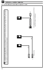
5.7.2
3-lead Resistance
Thermometer (RTD) Inputs
The three leads must have equal resistance, not
exceeding 50
Ω
each.
5.7.3
2-lead Resistance
Thermometer (RTD) Inputs
If long leads are necessary it is preferable to use a
3-lead RTD. If the RTD is to be used in a hazardous
area, a 3-lead RTD connected via a suitable Zener
barrier, must be used.
5.8
Output Connections
Make connections as shown in Fig 5.7.
Refer to rear fold-out/ Table B – Output
Sources for the default output assignment
settings.
5.9
Power Supply Connections
Warning.
•
A 1A fuse must be fitted in the live (+ve) supply line.
•
The ground line must be connected to the
ground stud and not to terminal 18 on the
terminal block – see Fig. 5.7.
Do not disturb the link between' terminal 18
and the ground stud.
•
The type of power supply required (a.c. or d.c.)
is stated at the time of order and can be
identified from the instrument code number:
C50X/XX0X/STD = 85 to 265V a.c.
C50X/XX1X/STD = 24V d.c.
Table 5.1 Thermocouple Compensating Cable
Содержание C505
Страница 1: ...ControlIT 1 2 DIN Advanced Process Controller C505 User Guide IM C505_6 ...
Страница 116: ...112 NOTES ...


