


10
1ZSE 5492-129 en, Rev. 6
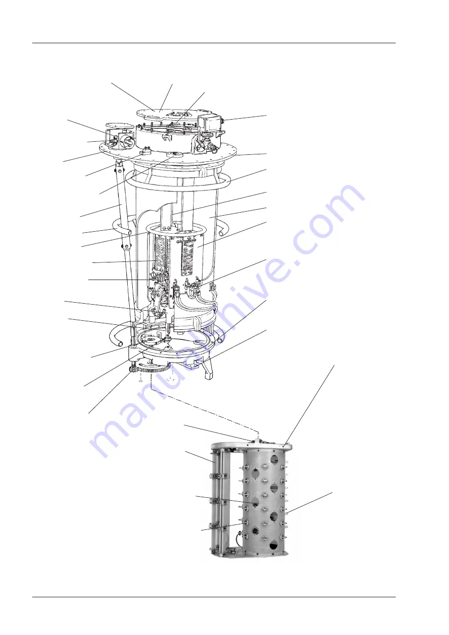
Bottom valve for
drying process
Pressure relay
Top-section
Shielding-ring
1)
Diverter switch
Plug-in contacts
Bottom section
Oil valve
Cover
Driving disc for the
diverter switch
Insulating cylinder
Draining tube
Guide-pins
Current terminal
Transition resistors
Fixed and moving
contacts
Intermediate gear
Insulating shaft
Bevel gear
Position indicator
Fig. 1. General arrangement of on-load tap-changer, type UC.
Earthing terminal
Serial No.
Diverter switch housing
Serial No.
Connection flange for
gas operated relay
Shielding-ring
2)
Shielding-ring
1)
1) Only at impulse withstand
voltage to earth of 650 kV
and 1050 kV
2) Not on UCG of the short type
Tap selector
Fixed fine-selector
contacts
Moving fine-
selector contacts
Change-over
selector
Geneva gear
Current collector
1. Introduction
Содержание BUE
Страница 6: ......
Страница 8: ......
Страница 19: ...19 1ZSE 5492 129 en Rev 6 fm_00237 Fig 5 Contact timing diagram BUE 2 Trouble shooting ...
Страница 21: ...21 1ZSE 5492 129 en Rev 6 Fig 7 Contact timing diagram BUL fm_00239 2 Trouble shooting ...


