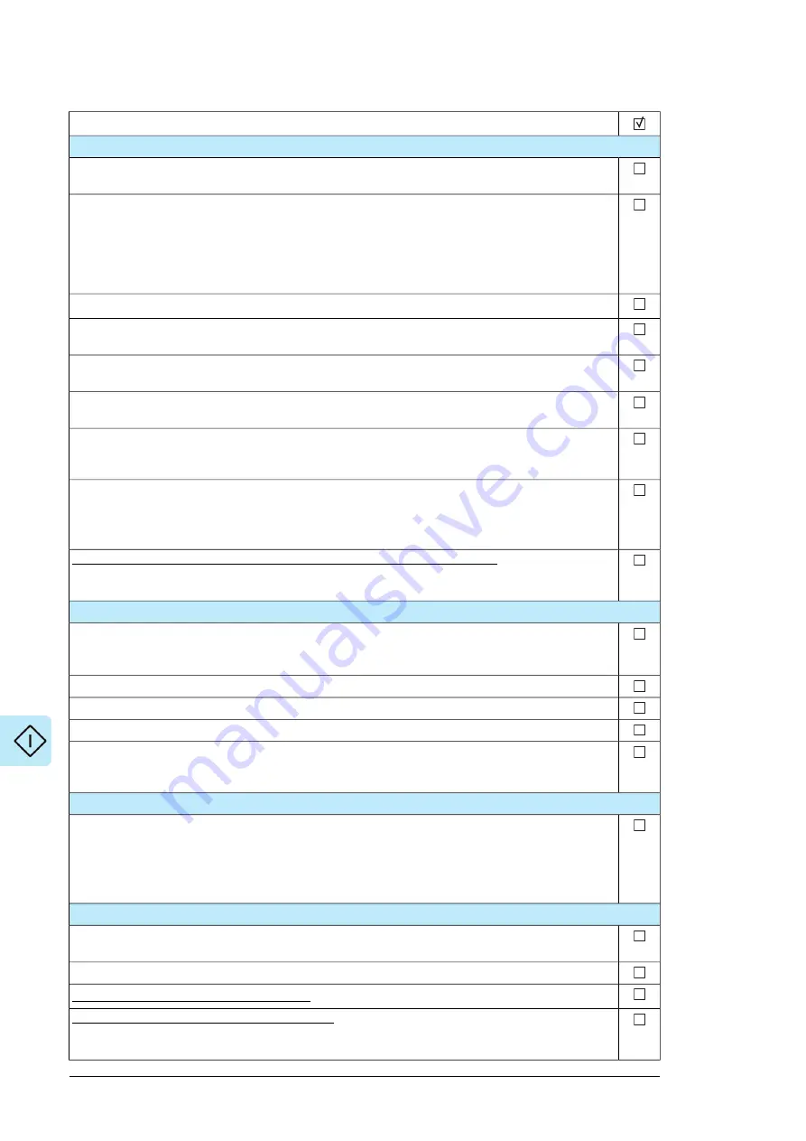
Action
Checks/Settings with no voltage connected
Ensure that the disconnector of the supply transformer is locked to the off (0) position, ie. no voltage
is, and cannot be connected to the drive inadvertently.
Check that the main switch-disconnector is switched off, or main breaker racked out. Both are external
customer equipment.
Note:
12-pulse and 24-pulse units may have multiple switch-disconnectors or breakers – check that all are
open before you proceed.
Check the mechanical and electrical installation of the drive. See
Installation checklist (page 117)
.
Check the settings of breakers/switches in the auxiliary circuits. See the circuit diagrams delivered with
the drive.
Check that the auxiliary voltage selector [X59] on the front plate of the inverter modules is set according
to actual auxiliary voltage (230 or 115 V AC).
Disconnect any unfinished or uninspected auxiliary voltage (115/230 V AC) cables that lead from the
terminal blocks to the outside of the equipment.
Check that both channels of the Safe torque off circuit connected to the STO inputs of both the supply
control unit [A51] and the inverter control unit [A41] are closed. Refer to the wiring diagrams delivered
with the drive.
If the Safe torque off functionality is used, check that the STO OUT output on the inverter control unit
(A41) is chained to the STO inputs of all inverter modules.
If the Safe torque off functionality is not used, check that the STO input on all inverter modules is correctly
wired to +24 V and ground.
Drives with ground fault monitoring for IT (ungrounded) systems (Q954): Adjust the settings of
the ground fault monitor to suit the installation. See the circuit diagrams of the delivery and
IRDH275B
Ground Fault Monitor Operating Manual
by Bender (code: TGH1386en).
Powering up the auxiliary circuit of the drive
Make sure that it is safe to connect voltage. Ensure that
• nobody is working on the drive or circuits that have been wired from outside into the drive cabinet
• the cover of the motor terminal box is in place.
Close the circuit breakers and/or fuse disconnectors supplying the auxiliary voltage circuits.
Close the cabinet doors.
Close the main breaker of the supply transformer.
Switch on the auxiliary voltage [Q20]. Also switch on the voltage to any other externally-supplied options
(such as the cooling fan supply, lighting, heating). If the drive is equipped with a cooling unit, close the
main switch of the coolant pump [Q200].
Setting up the supply unit parameters
Check the voltage range setting in parameter
195.01 Supply voltage
.
For more information on setting up the supply control program, see the
ACS880 diode supply control
program firmware manual
(3AUA0000103295 [English]).
If you need more information on the use of the control panel, see the
ACX-AP-x Assistant control
panels user's manual
(3AUA0000085685 [English]).
Setting up the inverter unit parameters, and performing the first start
Set up the inverter control program. See the appropriate start-up guide and/or firmware manual. There
is a separate start-up guide only for some control programs.
Check that parameter
95.09 Switch fuse controller
is set to
Disabled
.
Drives with a brake chopper (D150): See chapter
Drives with an fieldbus adapter module (optional): Set the fieldbus parameters. Activate the appropriate
assistant (if present) in the control program, or see the user’s manual of the fieldbus adapter module,
and the drive firmware manual. Check that the communication works between the drive and the PLC.
120 Start-up
Содержание ACS880-07CLC
Страница 1: ...ABB industrial drives Hardware manual ACS880 07CLC drives ...
Страница 2: ......
Страница 4: ......
Страница 64: ...64 ...
Страница 82: ...82 ...
Страница 91: ...PE PE 10 13 12 22 Electrical installation 91 ...
Страница 122: ...122 ...
Страница 124: ...124 ...
Страница 132: ...5 4 11 7 6 8 132 Maintenance ...
Страница 133: ...14 15 16 12 13 17 Maintenance 133 ...
Страница 141: ...5 Set the real time clock Maintenance 141 ...
Страница 142: ...142 ...
Страница 150: ...150 ...
Страница 176: ...ACS880 07CLC 0390A 7 C121 marine construction 176 Dimensions ...
Страница 177: ...ACS880 07CLC 1310A 7 Dimensions 177 ...
Страница 178: ...ACS880 07CLC 2180A 7 C121 marine construction 178 Dimensions ...
Страница 179: ...ACS880 07CLC 3260A 7 C121 marine construction Dimensions 179 ...
Страница 181: ... 2 D8D Dimensions 181 ...
Страница 182: ... 3 D8D 182 Dimensions ...
Страница 183: ... 4 D8D Dimensions 183 ...
Страница 185: ...Inverter module cubicle with two R8i modules bottom cable exit Dimensions 185 ...
Страница 186: ...Inverter module cubicle with three R8i modules bottom cable exit 186 Dimensions ...
Страница 187: ...Brake chopper cubicle D150 Dimensions 187 ...
Страница 188: ...188 ...
Страница 202: ...202 ...
Страница 211: ......
Страница 212: ......
Страница 214: ...Contact us www abb com drives 3AXD50000131457 Rev A EN EFFECTIVE 2018 03 09 3AXD50000131457A ...


