


Select the cables and fuses
Select the power cables. Obey local regulations.
•
Input power cable: Use symmetrical shielded cable (VFD cable) for the best EMC
performance. NEC installations: Conduit with continuous conductivity is also
allowed and must be grounded on both ends.
•
Motor cable: ABB recommends symmetrically shielded VFD motor cable to reduce
bearing current and wear and stress on motor insulation and to provide the best
EMC performance. Although not recommended, conductors inside continuously
conductive conduit is allowed in NEC installations. Ground conduit on both ends.
Use separate insulated ground from motor to drive inside the conduit.
•
Current rating: Max. load current.
•
Voltage rating (minimum): IEC installations: 600 V AC cable is accepted for up to
500 V AC, 750 VAC cable is accepted for up to 600 V AC, 1000 V AC cable is accepted
for up to 690 V AC. NEC installations: 600 V AC cable for 230 V AC motors and
1000 V AC cable for 480 V AC and 600 V AC motors. 600 V AC cable for 230 V AC
and 480 V AC power lines; 1000 V AC cable for 600 V AC power line.
•
Temperature rating: IEC installations: Select a cable rated for at least 70 °C
maximum permissible temperature of conductor in continuous use. NEC
installations: Use 75 °C conductors minimum. Insulation temperature can be higher
as long as the ampacity is based on 75 °C conductors.
Select the control cables.
•
Use double-shielded twisted-pair cable for analog signals. Use double-shielded
or single-shielded cable for the digital, relay and I/O signals. Do not run 24 V and
115/230 V signals in the same cable.
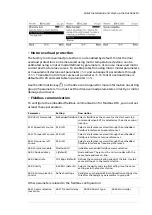
Protect the drive and input power cable with the correct fuses.
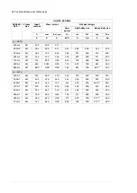
For typical power cable sizes, refer to section
Typical power cables (page 26)
For the correct fuses, refer to section
.
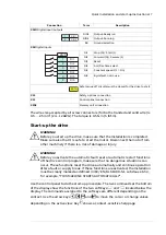
Examine the installation site
Examine the installation site. Make sure that:
•
The installation site is sufficiently ventilated or cooled to remove heat from the
drive. See the technical data.
•
The ambient conditions of the drive meet the specifications. See the technical
data.
•
The material behind, above and below the drive is non-flammable.
•
There is sufficient free space around the drive for cooling, maintenance, and
operation. See the free space specifications for the drive.
•
Make sure that there are no sources of strong magnetic fields such as high-current
single-core conductors or contactor coils near the drive. A strong magnetic field
can cause interference or inaccuracy in the operation of the drive.
Quick installation and start-up instructions 9
Содержание ACS880-04F
Страница 1: ...ABB INDUSTRIAL DRIVES ACS880 04F drive modules Quick installation and start up guide...
Страница 2: ......
Страница 4: ......
Страница 6: ...6...