background image

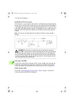
Electrical installation   113

Installation next to the control unit in frames R7 to R9

WARNING! 

Follow the safety instructions, page 

14

Ignoring the instructions 

can cause physical injury or death, or damage to the equipment.

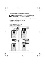
1. Disconnect the drive from the power line. Lock the main disconnecting device and 

ensure by measuring that there is no voltage.

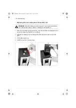
2. Remove the front cover (see page 

94

).

3. Insert the module carefully into its position.

4. Attach the module with four screws. 

Note:

 Correct installation of the grounding 

screw (a) is essential for fulfilling the EMC requirements and for proper operation 
of the module.

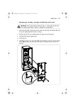
5. Tighten the grounding screw of the electronics. 

6. Connect the data communication cable to slot X110 on the module and to 

connector X12 on the drive control unit.

7. Connect the Safe torque off wires to connector X111 on the module and to 

connector XSTO on the drive module control unit as shown in section 

Wiring

  on 

page 

198

8. Connect the ex24 V power supply cable to connector X112.

9. Connect the other wires as shown in 

FSO-11 user’s manual

 (3AUA0000097054 

[English]).  

ACS880-01 HW.book  Page 113  Monday, July 1, 2013  4:51 PM

Содержание ACS880-01 Series

Страница 1: ...ABB industrial drives Hardware manual ACS880 01 drives 0 55 to 250 kW 0 75 to 350 hp ACS880 01 HW book Page 1 Monday July 1 2013 4 51 PM...

Страница 2: ...R1 to R3 3AUA0000085966 ACS880 01 quick installation guide for frames R4 and R5 3AUA0000099663 ACS880 01 quick installation guide for frames R6 to R9 3AUA0000099689 ACS880 01 cabinet installation supp...

Страница 3: ...Table of contents Mechanical installation Start up Hardware manual ACS880 01 drives 0 55 to 250 kW 0 75 to 350 hp 3AUA0000078093 Rev G EN EFFECTIVE 2013 07 01 2013 ABB Oy All Rights Reserved ACS880 0...

Страница 4: ...ACS880 01 HW book Page 4 Monday July 1 2013 4 51 PM...

Страница 5: ...manuals 22 Categorization by frame size and option code 22 Quick installation start up and operating flowchart 23 Terms and abbreviations 24 Safety data SIL PL 25 3 Operation principle and hardware d...

Страница 6: ...ts table 55 Additional requirements for ABB motors of types other than M2_ M3_ M4_ HX_ and AM_ 58 Additional requirements for ABB high output and IP23 motors 59 Additional requirements for non ABB hig...

Страница 7: ...ing the motor power supply from direct on line to drive 77 Protecting the contacts of relay outputs 77 Connecting a motor temperature sensor to the drive I O 79 6 Electrical installation What this cha...

Страница 8: ...r contains 121 Maintenance intervals 121 Preventive maintenance table 122 Heatsink 123 Fans 123 Replacing the main cooling fan of frames R1 to R3 124 Replacing the auxiliary cooling fan of IP55 frames...

Страница 9: ...nal and lead through data for the power cables 160 IEC 160 US 161 UL listed cable lugs and tools 162 Terminal data for the control cables 162 Electrical power network specification 163 Motor connectio...

Страница 10: ...tion What this chapter contains 197 Description 197 Compliance with the European Machinery Directive 198 Wiring 198 Activation switch 198 Cable types and lengths 198 Single drive internal power supply...

Страница 11: ...atings 217 Degree of protection of JBR SACE and SAFUR resistors 219 Terminals and cable lead through data 219 15 Common mode du dt and sine filters What this chapter contains 221 Common mode filters 2...

Страница 12: ...12 ACS880 01 HW book Page 12 Monday July 1 2013 4 51 PM...

Страница 13: ...conditions which can result in serious injury or death and or damage to the equipment and advise on how to avoid the danger The following warning symbols are used in this manual Electricity warning wa...

Страница 14: ...rcuits Externally supplied control circuits may cause dangerous voltages inside the drive even when the main power on the drive is switched off Do not make any insulation or voltage withstand tests on...

Страница 15: ...rbances In addition connect the cable shields to protective earth PE in order to meet safety regulations Do not install a drive with EMC filter option E200 or E202 on an ungrounded power system or a h...

Страница 16: ...tage on the drive power terminals according to step 1 or 2 or if possible according to the both steps 1 Disconnect the motor from the drive with a safety switch or by other means Check by measuring th...

Страница 17: ...The drive is heavy and its center of gravity is high An overturning unit can cause physical injury Beware of hot surfaces Some parts such as heatsinks of power semiconductors remain hot for a while a...

Страница 18: ...ed by the drive The drive can be adjusted to operate the motor at speeds above and below the speed provided by connecting the motor directly to the power line Do not activate any automatic fault reset...

Страница 19: ...t motor drives WARNING Do not run the motor over the rated speed Motor overspeed leads to overvoltage which may damage or explode the capacitors in the intermediate circuit of the drive ACS880 01 HW b...

Страница 20: ...20 Safety instructions ACS880 01 HW book Page 20 Monday July 1 2013 4 51 PM...

Страница 21: ...rical schematic symbols The manual is written for readers worldwide Both SI and imperial units are shown Contents of the manual This manual contains the instructions and information for the basic driv...

Страница 22: ...on its implementing Resistor braking describes selection protection and wiring of brake choppers and resistors The chapter also contains technical data Common mode du dt and sine filters describes se...

Страница 23: ...es and equipment are present and correct Mount the drive Mechanical installation page 41 or 43 If the drive has been non operational for more than one year the converter DC link capacitors need to be...

Страница 24: ...Optional TTL absolute encoder interface module FEN 21 Optional resolver interface module FEN 31 Optional HTL incremental encoder interface module FOA 01 Optional optical DDCS communication adapter mod...

Страница 25: ...life units the number of dangerous undetected failures during a particular measurement interval under stated conditions PFD IEC 61508 Probability of failure on demand PFHd IEC 61508 Probability of dan...

Страница 26: ...26 Introduction to the manual ACS880 01 HW book Page 26 Monday July 1 2013 4 51 PM...

Страница 27: ...pter contains This chapter briefly describes the operation principle and construction of the drive Product overview The ACS880 01 is a drive for controlling asynchronous AC induction motors permanent...

Страница 28: ...to alternating current and voltage 4 Brake chopper Conducts the surplus energy from the intermediate DC circuit of the drive to the brake resistor when necessary The chopper operates when the DC link...

Страница 29: ...1 The components of the standard IP21 drive are shown below view of frame R5 1 Control panel 2 Front cover 3 Cable entry box 4 Four fastening points at the back of the unit 5 Heatsink 6 Lifting holes...

Страница 30: ...ents of the IP55 drive option B056 are shown below view of frame R4 1 Control panel behind the control panel cover 2 Front cover 3 Four fastening points at the back of the unit 4 Heatsink 5 Lifting ho...

Страница 31: ...12 drive option B056 are shown below view of frame R6 1 Control panel behind the control panel cover 2 Front cover 3 Four fastening points at the back of the drive 4 Heatsink 5 Lifting holes 6 Hood i...

Страница 32: ...ection diagram page 100 and Control unit ZCU 12 connection data page 164 7 See section Control panel page 34 8 du dt common mode or sine filter optional see page 221 Slot 2 L1 L2 L3 PE U T1 V T2 W T3...

Страница 33: ...Digital input outputs XDI Digital inputs XSTO Safe torque off connection X12 Connector for safety functions modules optional X13 Control panel PC connection X202 Option slot 1 X203 Option slot 2 X204...

Страница 34: ...serial number which allow identification of each unit The type designation label is located on the front cover An example label is shown below No Description 1 Type designation see section Type desig...

Страница 35: ...function cable entry box brake chopper in frames R1 to R4 coated boards printed multilingual quick guides and CD containing all manuals Size xxxx Refer to the rating tables page 137 Voltage range 2 2...

Страница 36: ...er L516 FEN 21 resolver interface module L517 FEN 01 TTL incremental encoder interface module L518 FEN 11 absolute encoder interface module L525 FAIO 01 analog I O extension module L526 FDIO 01 digita...

Страница 37: ...Operation principle and hardware description 37 R713 Polish R714 Turkish CODE DESCRIPTION ACS880 01 HW book Page 37 Monday July 1 2013 4 51 PM...

Страница 38: ...38 Operation principle and hardware description ACS880 01 HW book Page 38 Monday July 1 2013 4 51 PM...

Страница 39: ...the mechanical installation of the drive Safety WARNING For frame sizes R6 to R9 Use the lifting eyes of the drive when you lift the drive Do not tilt the drive The drive is heavy and its center of g...

Страница 40: ...e section Losses cooling data and noise on page 157 The operation conditions of the drive agree with the specifications in section Ambient conditions page 167 The wall is vertical not flammable and st...

Страница 41: ...make sure that the drive is of the correct type Item Description Item Description 1 Drive with factory installed options Control cable grounding shelf Romex connectors in IP21 frames R1 to R3 in a pl...

Страница 42: ...rd sleeve 5 Lift the drive Frame R5 cable entry box IP21 UL Type 1 This illustration shows the contents of the cable entry box package The package also includes an assembly drawing which shows how to...

Страница 43: ...the correct type Item Description Item Description 1 Cable entry box Power and control cable grounding shelves in a plastic bag assembly drawing Note The cable entry box is mounted to the IP55 drive...

Страница 44: ...the lifting eyes of the drive Lift the drive with a hoist Frame R6 cable entry box IP21 UL Type 1 This illustration shows the contents of the cable entry box package The package also includes an assem...

Страница 45: ...ype 1 This illustration shows the contents of the cable entry box package The package also includes an assembly drawing which shows how to install the cable entry box to the drive module frame 3aua000...

Страница 46: ...1 UL Type 1 This illustration shows the contents of the cable entry box package There is also an assembly drawing which shows how to install the cable entry box to the drive module frame 3aua000011217...

Страница 47: ...ype 1 This illustration shows the contents of the cable entry box package The package also includes an assembly drawing which shows how to install the cable entry box to the drive module frame 3aua000...

Страница 48: ...and on the manuals CD Frames R1 to R4 1 See the dimensions in chapter Dimension drawings Mark the locations for the four mounting holes 2 Drill the mounting holes 3 Start the screws or bolts into the...

Страница 49: ...ion dampers on page 50 2 Put the hood onto the upper screws 3 Tighten the upper screws in the wall securely 4 Tighten the lower screws in the wall securely Note Do not open or remove the cable entry b...

Страница 50: ...Remove the front cover 5 For IP21 units Attach the cable entry box to the drive frame For instructions see the assembly drawing in the cable entry box A view of frame R5 is shown below 6 Position the...

Страница 51: ...Mechanical installation 51 6 1 2 3 Screw size R5 M5 R6 M8 R7 M8 R8 M8 R9 M8 3 200 mm 300 mm 7 87 11 81 4 5 7 ACS880 01 HW book Page 51 Monday July 1 2013 4 51 PM...

Страница 52: ...52 Mechanical installation Cabinet installation See ACS880 01 cabinet installation supplement 3AUA0000145446 English ACS880 01 HW book Page 52 Monday July 1 2013 4 51 PM...

Страница 53: ...ording to applicable local laws and regulations ABB does not assume any liability whatsoever for any installation which breaches the local laws and or other regulations Furthermore if the recommendati...

Страница 54: ...synchronous motor or AC induction servomotor with the drive Several induction motors can be connected to the drive at a time Select the motor size and drive type from to the rating tables in chapter...

Страница 55: ...and high switching frequencies can generate current pulses that flow through the motor bearings This can gradually erode the bearing races and rolling elements Optional du dt filters protect motor ins...

Страница 56: ...du dt N or Reinforced N 600 V UN 690 V cable length 150 m Reinforced du dt du dt N 600 V UN 690 V cable length 150 m Reinforced N Form wound HX_ and AM_ 380 V UN 690 V Standard n a N CMF Old form wou...

Страница 57: ...rosecond rise time N CMF If the intermediate DC circuit voltage of the drive is increased from the nominal level by resistor braking check with the motor manufacturer if additional output filters are...

Страница 58: ...e by up to 20 percent Consider this voltage increase when specifying the motor insulation requirements if the motor will be braking a large part of its operation time Example Motor insulation requirem...

Страница 59: ...wound motor series for example M3AA M3AP and M3BP Nominal mains voltage AC line voltage Requirement for Motor insulation system ABB du dt and common mode filters insulated N end motor bearings PN 100...

Страница 60: ...p or frame size NEMA 500 134 hp PN 469 hp or NEMA 500 frame size NEMA 580 UN 420 V Standard LL 1300 V N or CMF N CMF 420 V UN 500 V Standard LL 1300 V du dt N or CMF du dt N CMF or Reinforced LL 1600...

Страница 61: ...ble length proceed as follows Peak line to line voltage Read the relative LL UN value from the appropriate diagram below and multiply it by the nominal supply voltage UN Voltage rise time Read the rel...

Страница 62: ...ve peak line to line voltage du dt UN Relative du dt value Note LL and du dt values are approximately 20 higher with resistor braking LL UN l m du dt UN 1 s 1 0 2 0 5 0 4 0 3 0 1 5 2 5 3 5 4 5 100 200...

Страница 63: ...conductors of the cable should be at least 1 kV Use symmetrical shielded motor cable see page 66 for drive frame size R5 and larger or motors larger than 30 kW 40 hp A four conductor system can be us...

Страница 64: ...type Al cable type mm2 mm2 AWG kcmil AWG kcmil UN 208 240 V 04A6 2 R1 3 1 5 14 06A6 2 R1 3 1 5 14 07A5 2 R1 3 1 5 14 10A6 2 R1 3 1 5 14 16A8 2 R2 3 6 10 24A3 2 R2 3 6 10 031A 2 R3 3 10 8 046A 2 R4 3...

Страница 65: ...R1 3 1 5 14 04A8 5 R1 3 1 5 14 05A2 5 R1 3 1 5 14 07A6 5 R1 3 1 5 14 11A0 5 R1 3 1 5 14 014A 5 R2 3 6 10 021A 5 R2 3 6 10 027A 5 R3 3 10 8 034A 5 R3 3 10 8 040A 5 R4 3 16 3 25 6 052A 5 R4 3 25 3 25 4...

Страница 66: ...cepted cable sizes of the drive 3 The biggest cable size accepted by the connection terminals of frame R8 is 2 3 150 Biggest possible cable size is 3x240 or 400 MCM if the terminal type is changed and...

Страница 67: ...tor and a shield The PE conductor must meet the requirements of IEC 61439 1 A four conductor system three phase conductors and a protective conductor on a cable tray is not allowed for motor cabling i...

Страница 68: ...rmor cable with symmetrical grounds or shielded power cable for the motor cables if metallic conduit is not used For the North American market 600 V AC cable is accepted for up to 500 V AC 1000 V AC c...

Страница 69: ...ploy one individually shielded pair for each signal Do not use common return for different analog signals A double shielded cable figure a below is the best alternative for low voltage digital signals...

Страница 70: ...rallel runs of motor cables with other cables in order to decrease electromagnetic interference caused by the rapid changes in the drive output voltage Where control cables must cross power cables ens...

Страница 71: ...ween the drive and the motor European Union Install the equipment in a metal enclosure with 360 degree grounding for the shields of both the incoming and outgoing cable or connect the shields of the c...

Страница 72: ...ected to multiple motors use a separate circuit breaker or fuses for protecting each motor cable and motor against overload The drive overload protection is tuned for the total motor load It may not t...

Страница 73: ...on page 197 Note Pressing the stop key on the control panel of the drive does not generate an emergency stop of the motor or separate the drive from dangerous potential Implementing the Safe torque of...

Страница 74: ...ters to the motor cables between the drive and the motor They are not meant to be used with AC drives and can cause permanent damage to the drive or themselves If there are power factor compensation c...

Страница 75: ...r control operates extremely fast much faster than it takes for the contactor to open its contacts When the contactor starts opening while the drive controls the motor the DTC control will try to main...

Страница 76: ...ive main contactor on off control Q4 Bypass circuit breaker S40 Motor power supply selection drive or direct on line K1 Drive main contactor S41 Start when motor is connected direct on line K4 Bypass...

Страница 77: ...1 4 Start the drive and the motor with the drive control panel drive in local control mode or with the external start signal drive in remote control mode Protecting the contacts of relay outputs Induc...

Страница 78: ...78 Planning the electrical installation 1 Relay outputs 2 Varistor 3 RC filter 4 diode 230 V AC 230 V AC 24 V DC 1 2 3 4 ACS880 01 HW book Page 78 Monday July 1 2013 4 51 PM...

Страница 79: ...e digital inputs of the drive can be implemented in three alternate ways 1 There is double or reinforced insulation between the thermistor and live parts of the motor 2 Circuits connected to all digit...

Страница 80: ...80 Planning the electrical installation ACS880 01 HW book Page 80 Monday July 1 2013 4 51 PM...

Страница 81: ...y or death Checking the insulation of the assembly Drive Do not make any voltage tolerance or insulation resistance tests on any part of the drive as testing can damage the drive Every drive has been...

Страница 82: ...s instructions Note Moisture inside the motor casing will reduce the insulation resistance If moisture is suspected dry the motor and repeat the measurement Brake resistor assembly Check the insulatio...

Страница 83: ...h EMC AC and EMC DC on the skeleton See EMC filter disconnecting instructions for ACS880 01 drives with filters E200 and E202 3AUA0000125152 English For frame R4 contact ABB WARNING If a drive with EM...

Страница 84: ...ounding cable if the shield does not meet the requirements of IEC 61439 1 see page 63 and there is no symmetrically constructed grounding conductor in the cable see page 68 7 du dt filter or sine filt...

Страница 85: ...ector onto the stripped part of the cable IP55 units Tighten the clamps onto the stripped part of the cables 8 Connect the twisted shields of the power cables to the grounding terminals 9 Connect the...

Страница 86: ...86 Electrical installation 2 1 1 3 5 10 4 IP21 IP55 1 ACS880 01 HW book Page 86 Monday July 1 2013 4 51 PM...

Страница 87: ...llation 87 T3 W T2 V T1 U UDC R R L3 L2 L1 L1 L2 L3 T1 U T2 V T3 W R R UDC UDC N m N m R1 0 6 1 8 R2 0 6 1 8 R3 1 7 1 8 7 8 8 9 10 10 6b PE PE 9 8 6a PE PE 6b 8 8 ACS880 01 HW book Page 87 Monday July...

Страница 88: ...oles into the rubber grommets Slide the grommets onto the cables Slide the cables through the holes of the bottom plate and attach the grommets to the holes 7 Prepare the ends of the input power and m...

Страница 89: ...nd R terminals and tighten to the torque given in the figure 13 Reinstall the shroud on the power terminals 14 Secure the cables outside the unit mechanically Install the rubber grommets to the unused...

Страница 90: ...90 Electrical installation 2 1b 1a 4b 4 4a 3 3 IP55 IP21 1 ACS880 01 HW book Page 90 Monday July 1 2013 4 51 PM...

Страница 91: ...Electrical installation 91 6 6 7 5 PE PE 7 6 ACS880 01 HW book Page 91 Monday July 1 2013 4 51 PM...

Страница 92: ...92 Electrical installation 12 13 9 L1 L2 L3 T1 U T2 V T3 W N m R R UDC UDC N m N m R4 3 3 3 3 2 9 R5 15 15 2 9 8 9 10 9 10 11 ACS880 01 HW book Page 92 Monday July 1 2013 4 51 PM...

Страница 93: ...hrough the holes of the bottom plate and attach the grommets to the holes b 9 Tighten the clamp onto the stripped part of the cable 10 Fasten the twisted shields of the cables under the grounding clam...

Страница 94: ...94 Electrical installation 1a 2 1b 4 5a 3 2 5b 3 4 IP55 IP21 ACS880 01 HW book Page 94 Monday July 1 2013 4 51 PM...

Страница 95: ...Electrical installation 95 6 8a 7 PE PE 7 R8 R9 ACS880 01 HW book Page 95 Monday July 1 2013 4 51 PM...

Страница 96: ...96 Electrical installation 8b R8 R9 ACS880 01 HW book Page 96 Monday July 1 2013 4 51 PM...

Страница 97: ...R UDC UDC T Wire screw T Terminal nut T Wire screw T Terminal nut T M N m M N m M N m M N m N m R6 M10 30 M8 24 M8 20 M8 20 9 8 R7 M10 40 30 M8 24 M10 30 M10 30 9 8 R8 M10 40 M10 24 M10 40 M8 24 9 8...

Страница 98: ...98 Electrical installation 16 13 R8 R9 ACS880 01 HW book Page 98 Monday July 1 2013 4 51 PM...

Страница 99: ...n DC configurations of a number of drives allowing regenerative energy from one drive to be utilized by the other drives in motoring mode Contact your local ABB representative for further instructions...

Страница 100: ...30 V DC 2 A 2 COM 3 NO 1 NC Running 250 V AC 30 V DC 2 A 2 COM 3 NO 1 NC Faulted 1 250 V AC 30 V DC 2 A 2 COM 3 NO XD24 Digital interlock 1 DIIL By default not in use 2 24VD 24 V DC 200 mA 3 3 DICOM D...

Страница 101: ...Jumpers and switches DI4 Ramp times according to 0 Parameters 23 12 and 23 13 1 Parameters 23 14 and 23 15 Jumper Switch Description Positions J1 AI1 Determines whether analog input AI1 is used as a c...

Страница 102: ...Do not connect both ends of the cable shields directly to ground If a capacitor cannot be used at one end leave that end of the shield unconnected WARNING As the inputs pictured above are not insulat...

Страница 103: ...air cable 100 ohm for example PROFIBUS compatible cable for the wiring For best immunity high quality cable is recommended Keep the cable as short as possible the maximum length of the link is 50 mete...

Страница 104: ...closed By default the terminal block has jumpers to close the circuit Remove the jumpers before connecting an external Safe torque off circuitry to the drive See page 197 Safety functions X12 See sec...

Страница 105: ...tinuous as close to the terminals of the control unit as possible Secure the cables mechanically at the clamps below the control unit Frames R1 to R3 Ground also the pair cable shields and grounding w...

Страница 106: ...106 Electrical installation 6 5 7 7 1 5 N m 0 5 N m 3 3 1 5 N m ACS880 01 HW book Page 106 Monday July 1 2013 4 51 PM...

Страница 107: ...USB Type Mini B as follows 1 Lift the USB connector cover from bottom upwards 2 Insert the USB cable Mini B plug in the control panel USB connector 3 Insert the USB cable A plug in the USB connector...

Страница 108: ...45 connector 3 Connect the other end of the cable to the left hand side RJ 45 connector in the control panel housing of the first drive 4 Connect another cable to the right hand side RJ 45 connector i...

Страница 109: ...tional modules as follows WARNING Follow the safety instructions page 14 Ignoring the instructions can cause physical injury or death or damage to the equipment 1 Disconnect the drive from the power l...

Страница 110: ...fieldbus adapter and pulse encoder interface modules See the appropriate optional module manual for specific installation and wiring instructions See page 106 for the routing of the cables 3 4 5 ACS88...

Страница 111: ...mounting platform upwards to gain access to the optional module slots 4 Insert the module carefully into its position on the control unit 5 Attach the module with four screws Note The grounding screw...

Страница 112: ...112 Electrical installation 3 5 5a 5 5 6 X12 ACS880 01 HW book Page 112 Monday July 1 2013 4 51 PM...

Страница 113: ...ws Note Correct installation of the grounding screw a is essential for fulfilling the EMC requirements and for proper operation of the module 5 Tighten the grounding screw of the electronics 6 Connect...

Страница 114: ...114 Electrical installation X12 6 1 4 4a 4 4 5 ACS880 01 HW book Page 114 Monday July 1 2013 4 51 PM...

Страница 115: ...can cause injury or death Open the main disconnector of the drive and lock it to open position Measure to ensure that the drive is not powered Check that The ambient operating conditions meet the spe...

Страница 116: ...terminals have been tightened pull conductors to check The brake resistor cable if present has been connected to appropriate terminals and the terminals have been tightened pull conductors to check Th...

Страница 117: ...t up instructions given in Quick start up guide for ACS880 primary control program or in the firmware manual 2 Validate the Safe torque off function according to the instructions given in chapter Safe...

Страница 118: ...118 Start up ACS880 01 HW book Page 118 Monday July 1 2013 4 51 PM...

Страница 119: ...ages See the firmware manual for the descriptions causes and remedies of the drive control program warning and fault messages Where LED Color When the LED is lit Control panel mounting platform POWER...

Страница 120: ...120 Fault tracing ACS880 01 HW book Page 120 Monday July 1 2013 4 51 PM...

Страница 121: ...d by ABB The recommended maintenance intervals and component replacements are based on specified operational and environmental conditions ABB recommends annual drive inspections to ensure the highest...

Страница 122: ...apacitor reforming P P P P P P P P P P P P P P P P P P P P P Recommended annual cleanings by user Clean the IP22 Ul Type 1 and IP42 UL Type 1 Filtered inlet meshes on the cabinet door Clean the heatsi...

Страница 123: ...nd ensure by measuring that there is no voltage 2 Remove the cooling fan s See section Fans below 3 Blow clean compressed air not humid from bottom to top and simultaneously use a vacuum cleaner at th...

Страница 124: ...ath or damage to the equipment 1 Disconnect the drive from the power line Lock the main disconnecting device and ensure by measuring that there is no voltage 2 Release the retaining clip by pushing wi...

Страница 125: ...r line Lock the main disconnecting device and ensure by measuring that there is no voltage 2 Remove the front cover by undoing the mounting screws at the sides 3 Unplug the fan power supply wires 4 Li...

Страница 126: ...ipment 1 Disconnect the drive from the power line Lock the main disconnecting device and ensure by measuring that there is no voltage 2 Lift the fan mounting plate up from the front edge 3 Unplug the...

Страница 127: ...death or damage to the equipment 1 Disconnect the drive from the power line Lock the main disconnecting device and ensure by measuring that there is no voltage 2 Remove the front cover 3 Unplug the f...

Страница 128: ...power line Lock the main disconnecting device and ensure by measuring that there is no voltage 2 Undo the mounting screws of the fan mounting plate view from bottom below 3 Pull the fan mounting plate...

Страница 129: ...ice and ensure by measuring that there is no voltage 2 Remove the lower front cover see page 93 3 Unplug the control panel power supply wires from the control unit terminal X13 and the auxiliary cooli...

Страница 130: ...h or damage to the equipment 1 Disconnect the drive from the power line Lock the main disconnecting device and ensure by measuring that there is no voltage 2 Remove the IP55 front cover 3 Remove the l...

Страница 131: ...Maintenance 131 3 4 5 3 ACS880 01 HW book Page 131 Monday July 1 2013 4 51 PM...

Страница 132: ...Lock the main disconnecting device and ensure by measuring that there is no voltage 2 Undo the two mounting screws of the fan mounting plate view from drive bottom below 3 Turn the mounting plate down...

Страница 133: ...t 1 Disconnect the drive from the power line Lock the main disconnecting device and ensure by measuring that there is no voltage 2 Remove the front covers See section Connection procedure for frames R...

Страница 134: ...tic capacitors Their lifespan depends on the operating time of the drive loading and ambient temperature Capacitor life can be prolonged by lowering the ambient temperature In frames R1 to R3 the capa...

Страница 135: ...glish Memory unit When a drive is replaced the parameter settings can be retained by transferring the memory unit from the defective drive to the new drive The memory unit is located on the control un...

Страница 136: ...ery Dispose the old battery according to local disposal rules or applicable laws Replacing safety functions modules FSO 11 option Q973 Do not repair safety functions modules Replace a faulty module wi...

Страница 137: ...urrent Output ratings Nominal use Light overload use Heavy duty use I1N Imax IN PN ILd PLd IHd PHd A A A kW A kW A kW UN 208 240 V 04A6 2 R1 4 6 6 3 4 6 0 75 4 4 0 75 3 7 0 55 06A6 2 R1 6 6 7 8 6 6 1...

Страница 138: ...5 11 24 11 17 7 5 032A 3 R3 32 42 32 15 30 15 25 11 038A 3 R3 38 54 38 18 5 36 18 5 32 15 0 045A 3 R4 45 64 45 22 43 22 38 19 061A 3 R4 61 76 61 30 58 30 45 22 072A 3 R5 72 104 72 37 68 37 61 30 087A...

Страница 139: ...5 R4 40 64 40 22 38 22 34 19 052A 5 R4 52 76 52 30 49 30 40 22 065A 5 R5 65 104 65 37 62 37 52 30 077A 5 R5 77 122 77 45 73 45 65 37 096A 5 R6 96 148 96 55 91 55 77 45 124A 5 R6 124 178 124 75 118 75...

Страница 140: ...37 061A 7 R6 61 104 61 55 58 55 49 45 084A 7 R6 84 124 84 75 80 75 61 55 098A 7 R7 98 168 98 90 93 90 84 75 119A 7 R7 119 198 119 110 113 110 98 90 142A 7 R8 142 250 142 132 135 132 119 110 174A 7 R8...

Страница 141: ...1 2 2 3 0 7 5 1 5 2 0 16A8 2 R2 16 8 18 0 16 0 4 0 5 0 10 6 2 2 3 0 24A3 2 R2 24 3 28 6 23 1 5 5 7 5 16 8 4 0 5 0 031A 2 R3 31 0 41 29 3 7 5 10 24 3 5 5 7 5 046A 2 R4 46 64 44 11 15 38 7 5 10 061A 2 R...

Страница 142: ...25 052A 5 R4 52 76 52 30 40 40 22 30 065A 5 R5 65 104 65 37 50 52 30 40 077A 5 R5 77 122 77 45 60 65 37 50 096A 5 R6 96 148 96 55 75 77 45 60 124A 5 R6 124 178 124 75 100 96 55 75 156A 5 R7 156 247 1...

Страница 143: ...in light overload use Imax Maximum output current Available for 10 seconds at start then as long as allowed by drive temperature IHd Continuous rms output current allowing 50 overload for 1 minute eve...

Страница 144: ...k IP55 UL Type 12 drive type 240A 5 In the temperature range 40 50 C 104 122 F the rated output current is derated by 1 for every added 1 C 1 8 F In the temperature range 50 55 C 122 131 F the rated o...

Страница 145: ...protection on page 71 Note 2 Fuses with higher current rating than the recommended ones must not be used Smaller fuses can be used Note 3 Fuses from other manufacturers can be used if they meet the r...

Страница 146: ...ssmann 170M1566 000 061A 3 380 61 100 4650 690 Bussmann 170M1567 000 072A 3 480 72 125 8500 690 Bussmann 170M1568 000 087A 3 480 87 125 8500 690 Bussmann 170M1568 000 105A 3 700 105 160 16000 690 Buss...

Страница 147: ...30 275000 690 Bussmann 170M5812 2 UN 525 690 V 07A3 7 40 7 3 16 48 690 Bussmann 170M1559 000 09A8 7 53 9 8 20 78 690 Bussmann 170M1560 000 14A2 7 94 14 2 32 270 690 Bussmann 170M1562 000 018A 7 120 18...

Страница 148: ...7A 2 1300 87 125 100000 500 ABB OFAF00H125 00 115A 2 1700 115 160 170000 500 ABB OFAF00H160 00 145A 2 2300 145 200 300000 500 ABB OFAF0H200 0 UN 380 415 V 02A4 3 17 2 4 4 53 500 ABB OFAF000H4 000 03A3...

Страница 149: ...500 ABB OFAF000H100 000 077A 5 1000 77 100 63600 500 ABB OFAF000H100 000 096A 5 1300 96 125 103000 500 ABB OFAF00H125 00 124A 5 1700 124 160 185000 500 ABB OFAF00H160 00 UN 525 690 V 07A3 7 115 7 3 1...

Страница 150: ...1 5 3 3 4 3 1 1 1 2 10A6 2 3 1 5 3 3 4 3 1 5 1 8 16A8 2 3 6 5 5 5 8 1 8 1 8 24A3 2 3 6 9 7 11 3 3 3 5 031A 2 3 10 11 12 4 4 4 6 046A 2 3 16 3 35 14 15 7 7 8 2 061A 2 3 25 3 35 22 24 8 3 8 6 075A 2 3...

Страница 151: ...5 3 35 3 70 60 61 63 29 29 30 096A 5 3 50 3 70 78 80 83 42 43 45 124A 5 3 95 3 120 103 105 108 57 59 61 UN 525 690 V 07A3 7 3 1 5 9 5 9 7 10 4 3 3 3 3 3 5 09A8 7 3 1 5 12 12 14 4 4 4 5 4 7 14A2 7 3 2...

Страница 152: ...o line voltage V Rc cable resistance ohm Zk zk UN 2 SN transformer impedance ohm zk transformer impedance UN transformer rated voltage V SN nominal apparent power of the transformer kVA Xc cable react...

Страница 153: ...R6 and below 0 1 seconds for units of frame sizes R7 to R9 Follow local regulations Note 1 See also Implementing thermal overload and short circuit protection on page 71 Note 2 Fuses with higher curre...

Страница 154: ...JJS 300 T 274A 2 274 400 600 Bussmann JJS 400 T UN 440 480 V 02A1 5 2 1 3 600 Bussmann JJS 3 T 03A0 5 3 0 6 600 Bussmann JJS 6 T 03A4 5 3 4 6 600 Bussmann JJS 6 T 04A8 5 4 8 10 600 Bussmann JJS 10 T 0...

Страница 155: ...ussmann JJS 400 T 361A 5 361 500 600 Bussmann JJS 500 T 414A 5 414 600 600 Bussmann JJS 600 T Drive type ACS880 01 Input current Fuse one fuse per phase A A V Manufacturer Type UL class ACS880 01 HW b...

Страница 156: ...55 226 6 15 94 14 57 6 10 8 89 13 R2 405 370 155 249 8 15 94 14 57 6 10 9 80 18 R3 471 420 172 261 10 18 54 16 54 6 77 10 28 22 R4 576 490 203 274 18 5 22 70 19 30 7 99 10 80 41 R5 730 596 203 274 23...

Страница 157: ...256 940 67 170A 2 R7 450 265 1260 67 206A 2 R7 450 265 1500 67 274A 2 R8 550 324 2100 65 UN 380 415 V 02A4 3 R1 44 26 30 46 03A3 3 R1 44 26 40 46 04A0 3 R1 44 26 52 46 05A6 3 R1 44 26 73 46 07A2 3 R1...

Страница 158: ...0 165 1120 62 096A 5 R6 435 256 1295 67 124A 5 R6 435 256 1440 67 156A 5 R7 450 265 1940 67 180A 5 R7 450 265 2310 67 240A 5 R8 550 324 3300 65 260A 5 R8 550 324 3900 65 302A 5 R9 1150 677 4200 68 361...

Страница 159: ...67 119A 7 R7 450 265 2310 67 142A 7 R8 550 324 3300 65 174A 7 R8 550 324 3900 65 210A 7 R9 1150 677 4200 68 271A 7 R9 1150 677 4800 68 Drive type ACS880 01 Frame Air flow Heat dissipation Noise m3 h f...

Страница 160: ...2 N m R1 1 17 0 75 6 0 6 8 25 1 8 R2 1 17 0 75 6 0 6 8 25 1 8 R3 1 21 0 5 16 1 7 10 25 1 8 R4 1 24 0 5 35 3 3 18 25 2 9 R5 1 32 6 70 M8 15 18 35 2 9 R6 1 45 25 150 M10 30 30 185 9 8 R7 1 54 95 240 25...

Страница 161: ...18 10 0 4 0 31 4 1 3 R3 1 0 83 20 6 1 3 0 39 4 1 3 R4 1 0 94 20 2 2 4 0 70 4 2 1 R5 1 1 26 4 1 0 M8 11 0 0 70 2 2 1 R6 1 1 77 3 300 MCM M10 22 1 1 18 350 MCM 7 2 R7 1 2 13 4 0 400 MCM 3 300 MCM M10 29...

Страница 162: ...1 Ilsco CCL 4 38 Ilsco MT 25 1 2 Thomas Betts 54143TB 54142TB Thomas Betts TBM4S TBM4S 1 Burndy YA2C L4BOX Burndy MY29 3 2 Ilsco CRC 2 Ilsco IDT 12 1 Ilsco CCL 2 38 Ilsco MT 25 1 1 Thomas Betts 54148...

Страница 163: ...e 17 s Imbalance Max 3 of nominal phase to phase input voltage Fundamental power factor cos phi1 0 98 at nominal load Motor connection data Motor types Asynchronous AC induction motors permanent magne...

Страница 164: ...n alternatively be used as an input for PTC sensors 0 4 kohm 1 1 5 kohm Imax 15 mA for DI6 5 mA Start interlock input DIIL XD24 1 Connector pitch 5 mm wire size 2 5 mm2 24 V logic levels 0 5 V 1 15 V...

Страница 165: ...s AO1 and AO2 XAO Connector pitch 5 mm wire size 2 5 mm2 0 20 mA Rload 500 ohm Frequency range 0 300 Hz Resolution 11 bit sign bit Inaccuracy 2 of full scale range Drive to drive link XD2D Connector p...

Страница 166: ...4 DIIL 1 24VD 2 DICOM 3 24VD 4 DIOGND 5 XDIO DIO1 1 DIO2 2 XDI DI1 1 DI2 2 DI3 3 DI4 4 DI5 5 DI6 6 XSTO OUT1 1 SGND 2 IN1 3 IN2 4 J6 Ground Common mode voltage between channels 30 V Switch J6 settings...

Страница 167: ...ft above sea level 2 0 to 2000 m 6561 ft above sea level Above 1000 m 3281 ft see page 145 1 for neutral grounded TN and TT systems and non corner grounded IT systems 2 for corner grounded TN TT and I...

Страница 168: ...coated steel sheet 1 5 to 2 5 mm thickness of coating 100 micrometers color NCS 1502 Y Package Plywood and cardboard Foam cushions PP E bands PP Disposal The main parts of the drive can be recycled to...

Страница 169: ...of machinery Electrical equipment of machines Part 1 General requirements Provisions for compliance The final assembler of the machine is responsible for installing emergency stop device supply discon...

Страница 170: ...electronic product which is covered by the European Low Voltage Directive However the drive includes the Safe torque off function and can be equipped with other safety functions for machinery which as...

Страница 171: ...Technical data 171 Declaration of Conformity ACS880 01 HW book Page 171 Monday July 1 2013 4 51 PM...

Страница 172: ...172 Technical data ACS880 01 HW book Page 172 Monday July 1 2013 4 51 PM...

Страница 173: ...than 1000 V and intended for use in the second environment and not intended for use in the first environment Drive of category C4 drive of rated voltage equal to or above 1000 V or rated current equa...

Страница 174: ...of the standard can be met as follows 1 It is ensured that no excessive emission is propagated to neighboring low voltage networks In some cases the inherent suppression in transformers and cables is...

Страница 175: ...current The current is derated for 40 to 55 C 104 to 131 F The drive is suitable for use in a circuit capable of delivering not more than 100 000 rms symmetrical amperes 600 V maximum The ampere rati...

Страница 176: ...pending for drives of voltage ranges 204 240 V and 525 690 V For fulfilling the requirements of the standard see section Compliance with the EN 61800 3 2004 on page 173 GOST R certificate of conformi...

Страница 177: ...Dimension drawings 177 12 Dimension drawings What this chapter contains This chapter contains dimension drawings of the drive ACS880 01 HW book Page 177 Monday July 1 2013 4 51 PM...

Страница 178: ...178 Dimension drawings Frame R1 IP21 UL Type 1 3AUA0000097621 ACS880 01 HW book Page 178 Monday July 1 2013 4 51 PM...

Страница 179: ...Dimension drawings 179 Frame R2 IP21 UL Type 1 3AUA0000097691 ACS880 01 HW book Page 179 Monday July 1 2013 4 51 PM...

Страница 180: ...180 Dimension drawings Frame R3 IP21 UL Type 1 3AUA0000097847 ACS880 01 HW book Page 180 Monday July 1 2013 4 51 PM...

Страница 181: ...98 3 86 475 18 70 SUGGESTED MOUNTING HOLES 505 19 88 490 19 291 WITHOUT GLAND BOX 7 26 203 7 99 13 51 22 85 8 32 18 72 7 26 15 57 22 85 7 28 PLATE HOLE 44 1 73 3pcs GROMMET UP TO 24 0 94 CABLE DIAMETE...

Страница 182: ...MOUNTING HOLES 612 24 07 596 23 46 WITHOUT GLAND BOX 7 26 274 10 77 65 2 55 74 2 90 48 1 88 730 28 73 203 7 99 124 4 86 7 26 8 32 22 85 A B PLATE HOLE 51 2 01 3pcs GROMMET UP TO 32 1 26 CABLE DIAMETE...

Страница 183: ...Dimension drawings 183 Frame R6 IP21 UL Type 1 3AUA0000098321 ACS880 01 HW book Page 183 Monday July 1 2013 4 51 PM...

Страница 184: ...184 Dimension drawings Frame R7 IP21 UL Type 1 3AUA0000073149 ACS880 01 HW book Page 184 Monday July 1 2013 4 51 PM...

Страница 185: ...Dimension drawings 185 Frame R8 IP21 UL Type 1 3AUA0000073150 ACS880 01 HW book Page 185 Monday July 1 2013 4 51 PM...

Страница 186: ...186 Dimension drawings Frame R9 IP21 UL Type 1 3AUA0000073151 ACS880 01 HW book Page 186 Monday July 1 2013 4 51 PM...

Страница 187: ...Dimension drawings 187 Frame R1 IP55 UL Type 12 3AUA0000097621 ACS880 01 HW book Page 187 Monday July 1 2013 4 51 PM...

Страница 188: ...188 Dimension drawings Frame R2 IP55 UL Type 12 3AUA0000097691 ACS880 01 HW book Page 188 Monday July 1 2013 4 51 PM...

Страница 189: ...Dimension drawings 189 Frame R3 IP55 UL Type 12 3AUA0000097847 ACS880 01 HW book Page 189 Monday July 1 2013 4 51 PM...

Страница 190: ...53 160 6 30 SUGGESTED MOUNTING HOLES 98 3 86 475 18 70 SUGGESTED MOUNTING HOLES 505 19 88 490 19 291 7 28 22 85 22 85 8 32 18 72 PLATE HOLE 44 1 73 3pcs GROMMET UP TO 24 0 94 CABLE DIAMETER PLATE HOL...

Страница 191: ...NTING HOLES 581 22 87 SUGGESTED MOUNTING HOLES 612 24 07 7 26 596 23 46 WITHOUT GLAND BOX 344 13 53 54 2 11 96 3 78 730 28 73 29 1 13 165 6 51 A B PLATE HOLE 29 1 12 GROMMET UP TO 22 0 87 CABLE DIAMET...

Страница 192: ...192 Dimension drawings Frame R6 IP55 UL Type 12 3AUA0000098321 ACS880 01 HW book Page 192 Monday July 1 2013 4 51 PM...

Страница 193: ...Dimension drawings 193 Frame R7 IP55 UL Type 12 3AUA0000073149 ACS880 01 HW book Page 193 Monday July 1 2013 4 51 PM...

Страница 194: ...194 Dimension drawings Frame R8 IP55 UL Type 12 3AUA0000073150 ACS880 01 HW book Page 194 Monday July 1 2013 4 51 PM...

Страница 195: ...Dimension drawings 195 Frame R9 IP55 UL Type 12 3AUA0000073151 ACS880 01 HW book Page 195 Monday July 1 2013 4 51 PM...

Страница 196: ...196 Dimension drawings ACS880 01 HW book Page 196 Monday July 1 2013 4 51 PM...

Страница 197: ...rk on non electrical parts of the machinery without switching off the power supply to the drive When activated the Safe torque off function disables the control voltage of the power semiconductors of...

Страница 198: ...ernal 24 V DC power supply is used page 202 For information on the specifications of the STO input see section Control unit ZCU 12 connection data on page 164 Activation switch In the wiring diagrams...

Страница 199: ...witch K and drive control unit 60 m 200 ft between multiple drives 60 m 200 ft between external power supply and first drive Note that the voltage at the INx terminals of each drive must be at least 1...

Страница 200: ...200 Safe Torque off function Single drive internal power supply 24 V OUT1 SGND IN1 IN2 ACS880 01 ZCU T1 U T2 V T3 W UDC UDC A Control logic K ACS880 01 HW book Page 200 Monday July 1 2013 4 51 PM...

Страница 201: ...off function 201 Multiple drives internal power supply OUT1 SGND IN1 IN2 ACS880 01 ZCU OUT1 SGND IN1 IN2 ACS880 01 ZCU K 24 V OUT1 SGND IN1 IN2 ACS880 01 ZCU ACS880 01 HW book Page 201 Monday July 1 2...

Страница 202: ...off function Multiple drives external power supply 24 V OUT1 ACS880 01 ZCU OUT1 SGND IN1 IN2 ACS880 01 ZCU OUT1 SGND IN1 IN2 ACS880 01 ZCU 24 V DC K SGND IN1 IN2 ACS880 01 HW book Page 202 Monday July...

Страница 203: ...the machine must validate the function by performing an acceptance test The acceptance test must be performed at initial start up of the safety function after any changes related to the safety functi...

Страница 204: ...rates as follows Open the STO circuit The drive generates an indication if one is defined for stopped state in parameter 31 22 see the firmware manual Give a start command to verify that the STO funct...

Страница 205: ...agnet or synchronous reluctance SynRM motors only In case of a multiple IGBT power semiconductor failure the drive system can produce an alignment torque which maximally rotates the motor shaft by 180...

Страница 206: ...rformed and the drive trips on an STO hardware failure fault An attempt to use the STO in a non redundant manner for example activating only one channel will trigger the same reaction See the drive fi...

Страница 207: ...t circuit on printed circuit board has been made EN 13849 2 table D 5 The analysis is based on an assumption that one failure occurs at one time No accumulated failures have been analyzed R9 3 3 84E 0...

Страница 208: ...s typical 5 ms maximum Fault detection time Channels in different states for longer than 200 ms Fault reaction time Fault detection time 10 ms STO fault indication parameter 31 22 delay 500 ms STO war...

Страница 209: ...Safe Torque off function 209 Certificate ACS880 01 HW book Page 209 Monday July 1 2013 4 51 PM...

Страница 210: ...210 Safe Torque off function ACS880 01 HW book Page 210 Monday July 1 2013 4 51 PM...

Страница 211: ...opper connects the brake resistor to the intermediate DC circuit whenever the voltage in the circuit exceeds the limit defined by the control program Energy consumption by the resistor losses lowers t...

Страница 212: ...ur resistor assembly in which two standard resistors are connected in parallel two in series The ER value of the four resistor assembly is four times the value specified for the standard resistor Sele...

Страница 213: ...mum length of the resistor cable s is 10 m 33 ft EMC compliance of the complete installation Note ABB has not verified that the EMC requirements are fulfilled with external user defined brake resistor...

Страница 214: ...ve in a fault situation An example wiring diagram is shown below ABB resistors are equipped with a thermal switch 1 inside the resistor assembly as standard The switch indicates overtemperature and ov...

Страница 215: ...sulation of the assembly Follow the instructions given under Brake resistor assembly on page 82 Connection diagram See section Connection diagram on page 84 Connection procedure Connect the resistor c...

Страница 216: ...application For frames R5 to R9 Set parameter 43 07 Brake chopper runtime enable to Other bit and select from parameter 10 01 DI status the digital input where the thermal switch of the brake resistor...

Страница 217: ...2 45 2 4 SAFUR200F500 2 7 5400 13 5 ACS880 01 206A 2 55 2 4 SAFUR200F500 2 7 5400 13 5 ACS880 01 274A 2 75 1 8 2 SAFUR125F500 2 7200 18 UN 380 415 V ACS880 01 02A4 3 0 75 210 2 JBR 01 240 44 0 21 ACS...

Страница 218: ...5 22 13 SACE15RE13 13 435 2 ACS880 01 052A 5 22 13 SACE15RE13 13 435 2 ACS880 01 065A 5 37 8 SAFUR90F575 8 1800 4 5 ACS880 01 077A 5 45 8 SAFUR90F575 8 1800 4 5 ACS880 01 096A 5 55 5 4 SAFUR80F500 6 2...

Страница 219: ...ee section Terminal and lead through data for the power cables on page 160 ACS880 01 035A 7 33 18 SACE15RE22 22 420 2 ACS880 01 042A 7 45 18 SACE15RE22 22 420 2 ACS880 01 049A 7 45 18 SACE15RE22 22 42...

Страница 220: ...220 Resistor braking ACS880 01 HW book Page 220 Monday July 1 2013 4 51 PM...

Страница 221: ...ecking the compatibility of the motor and drive page 54 A common mode filter kit is available from ABB with order number is 64315811 for the drive The kit includes three wound cores For installation i...

Страница 222: ...X 09A4 3 NOCH0016 6X 07A6 5 NOCH0016 6X 026A 7 NOCH0030 6X 12A6 3 NOCH0016 6X 11A0 5 NOCH0016 6X 035A 7 NOCH0070 6X 017A 3 NOCH0016 6X 014A 5 NOCH0016 6X 042A 7 NOCH0070 6X 025A 3 NOCH0030 6X 021A 5 N...

Страница 223: ...ning navigate to www abb com drives and select Training courses Providing feedback on ABB Drives manuals Your comments on our manuals are welcome Go to www abb com drives and select Document Library M...

Страница 224: ...Contact us www abb com drives www abb com drivespartners 3AUA0000078093 Rev G EN EFFECTIVE 2013 07 01 ACS880 01 HW book Page 224 Monday July 1 2013 4 51 PM...

Отзывы: