ABB 9408 700 Скачать руководство пользователя страница 12

10

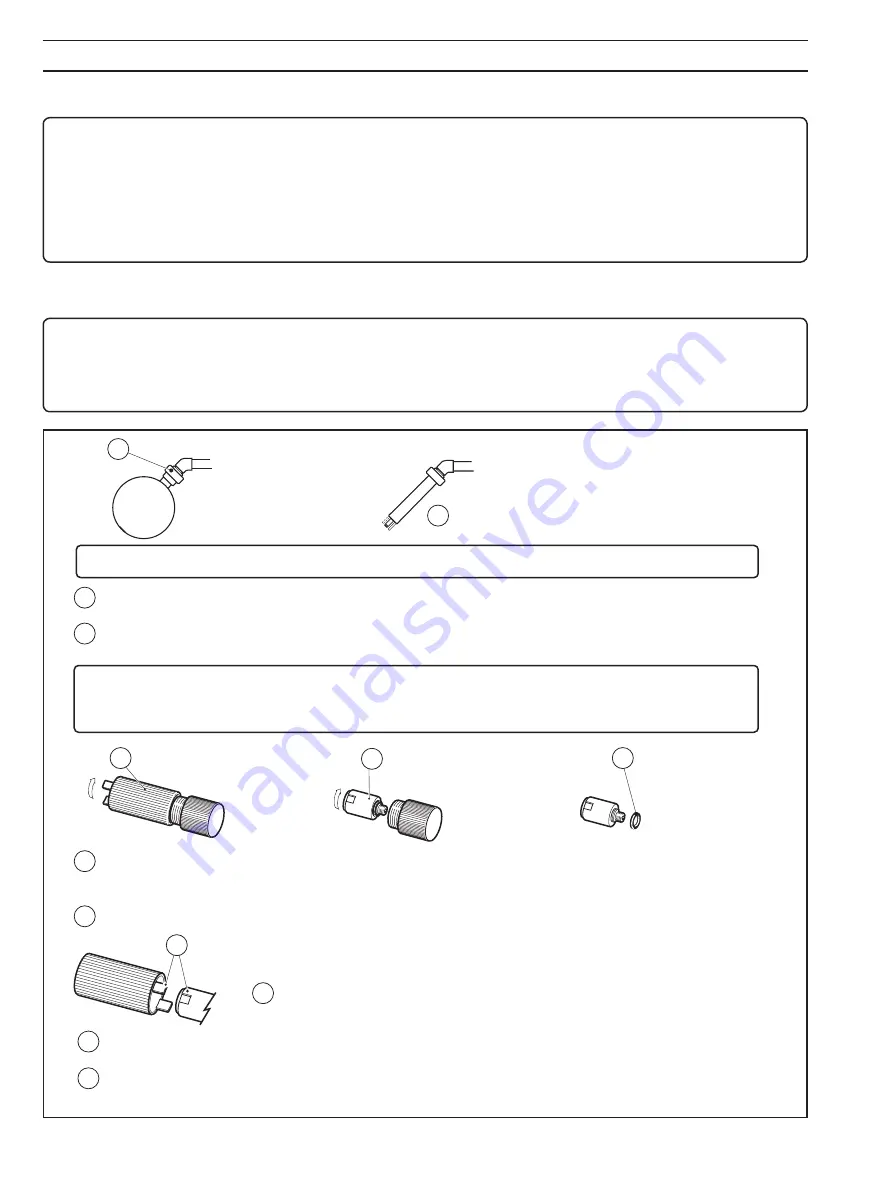
Access  the  new  capsule  by

unscrewing the capsule housing

Unscrew the capsule from the

shorting cap using the reverse end

of the capsule housing as a tool.

Remove and discard

the  rubber  sealing

ring  from  the  new

capsule.

Dry the capsule with a paper tissue taking care not to damage the delicate, transparent membrane covering

the silver cathode. Ensure that the gold contacts, and the threaded portion of the capsule are clean and

completely dry.
Fit the new sealing ring supplied – see 

7

 above and screw the capsule into the sensor block by hand, firmly.

Tighten the securing ring whilst restraining the ball from turning; rotation of the ball may damage the sensing

end of the system.

Caution. Clean and dry the area around the sensor capsule before removal, as indicated below.

Use the capsule housing as a tool to unscrew the old capsule from the sensor block (see 

0

 for method);

discard the old capsule in accordance with local regulations.
Dry the sensor block with a paper tissue; ensure that the gold electrical contacts, and the recess into

which the capsule screws, are clean and completely dry.

Unscrew the securing ring whilst restraining the ball from turning.

Remove the ball from the sensor pipe.

Reverse the capsule housing and locate the lugs into the keyways on top of the capsule.Then

using the capsule housing as a tool, tighten the the sensor firmly by hand to ensure a good

seal.

Calibrate the sensor - see Section 4.2 Calibrating the Sensor.

Caution.

• Do not leave the new capsule exposed to air for more than 30 minutes as the membrane will dry out.
• Ensure the following steps are done carefully to avoid damaging the membrane covering the silver cathode.

Align the holes in the end of the ball with the protruding sensor capsule and temperature compensator and

replace the ball assembly over the sensor pipe. Ensure that an 'O' ring is in place in the union half.

1

3

2

4

5

6

7

8

9

10

11

12

13

5.1  Replacing the Oxygen Sensor Capsule

5.1.1  Floating Ball System – Fig. 5.1

Refer to Fig. 3.2 for information about accessing the floating ball. Use the necessary procedure steps in reverse order.

Notes.

•  For systems fitted with the standard bracket the boom will have to be freed from the bracket clamp to access the floating 

ball.

•  For systems fitted with a swivel bracket, when the boom is in the horizontal position, unscrew the swivel plate locking 

bolt sufficiently to release the swivel plate. Swing the boom so that the floating ball is accessible.

Fig. 5.1 Replacing the Oxygen Sensor Capsule

5 MAINTENANCE

Storage

DO:

—   use sensors in date rotation to prevent them being  

stored longer than necessary.

—  at all times, store sensors in a dry and cool environment.

—  store sensors in a refrigerator to extend their life, but 

DO NOT allow them to freeze.

DO NOT:

—  allow sensors to dry out, either in storage or in use.

—  leave sensors in vehicles where they are likely to freeze or be 

exposed to high temperatures.

—  leave sensors on-site without protection from direct sun or 

high temperatures.

—  use the sensor if it's sealed environment has dried out.

Содержание 9408 700

Страница 1: ...xygen system comprises a flat ended sensor mounted into a relatively large diameter spherical flotation collar This form of construction presents to the sample a surface on which it is difficult for rags and other large solids to lodge For more demanding applications on line cleaning is available using the water wash option 9408 series Dissolved oxygen systems ...

Страница 2: ... more information Further publications are available for free download from www abb com analytical or by scanning this code Search for or click on 9408 series Dissolved oxygen systems Data Sheet DS 9408 EN ...

Страница 3: ...npacking 2 2 2 Floating Ball System 2 2 2 1 Assembled Version 2 2 2 2 Kit Version 2 2 3 Dip Systems 3 2 3 1 Assembled Version 3 2 3 2 Kit Version 3 2 4 Submersible System 3 3 MECHANICAL INSTALLATION 4 3 1 Assembling Kit Systems 4 3 1 1 Floating Ball 4 3 1 2 Dip 5 3 2 Installation 6 3 2 1 Floating Ball System 6 3 2 2 Dip Systems 7 3 2 3 Submersible Systems 7 3 3 Water Supply for Water Wash Systems ...

Страница 4: ...I T P O M E T S Y S d r a d n a t S r e t a w h t i W h s a W h s a W h s a W h s a W h s a W c i r t e M 0 5 7 8 0 4 9 2 5 7 8 0 4 9 l a i r e p m I 0 6 7 8 0 4 9 2 6 7 8 0 4 9 s n o i s n e m i D e p i P c i r t e M 0 1 N P t w 3 3 x m m 0 5 d o e p i p S B A l a i r e p m I E s s a l C t w 5 4 x B N 2 1 1 e p i p S B A 2 1 Unpacking After carefully removing the 9408 system from its packing chec...

Страница 5: ...o scale Ø40 mm User supplied tube ABS or PVC 1 9 inches O D Contents 1 Top cap with fixing screw 2 Adaptor 3 Shroud 4 Sensor block with cable attached and dummy sensor fitted 5 Dissovled oxygen sensor capsule 6 Tangit Solvent Cement not provided Contents 1 Top cap with fixing screw 2 Adaptor 3 Shroud 4 Sensor block with cable and water wash tube attached and dummy sensor fitted 5 Dissovled oxygen ...

Страница 6: ...4 4 5 4 3 1 Assembling Kit Systems 3 1 1 Floating Ball Fig 3 1 For installation of the assembled unit see Section 3 2 1 Floating Ball System Fig 3 1 Floating Ball Kit Assembly 3 MECHANICAL INSTALLATION ...

Страница 7: ...5 3 MECHANICAL INSTALLATION 3 1 2 Dip Fig 3 2 For installation of the assembled unit see Section 3 2 2 Dip Systems Fig 3 2 Dip Kit Assembly ...

Страница 8: ...nt cable slack for positioning servicing procedure Make the necessary electrical connections see Section 4 ELECTRICAL INSTALLATION If applicable arrange to have a water wash mains supply available see Section 3 3 and connect to the quick fit connector on the end cap 1 3 2 5 6 4 Standard Swivel Standard Swivel C Standard Swivel C 30 Viewed from above 3 2 Installation Caution The system is supplied ...

Страница 9: ...rovided This is to prevent cable strain and allows the system to be lowered to the required depth 3 2 2 Dip Systems Fig 3 4 Note The standard dip system is supplied with the temperature probe and oxygen sensor body fitted Before fitting the dip tube to any bracket or fixing remove the protective shroud unscrew the dummy capsule from the end of the oxygen sensor body and fit the oxygen sensor capsu...

Страница 10: ...cal water authority and council bylaws Caution The maximum water pressure at the electrode should not exceed 50psi 4 bar At NO time should the sample pressure be allowed to exceed that of the water wash water supply Fit a non return valve if this possibility exists Information As all quick fit connectors used in Water Wash systems incorporate cutoff valves tubes may subsequently be disconnected on...

Страница 11: ...ively 4 2 Calibrating the Sensor Fig 4 1 The procedures for zero and span calibration are fully described in the 4600 Series Transmitter Unit Operating Instructions to which reference should be made Note It is advisable to switch off the water wash before starting the calibration procedure This can be done either by turning off at the 4600 transmitter unit or by disconnecting the quick fit connect...

Страница 12: ... Section 4 2 Calibrating the Sensor Caution Do not leave the new capsule exposed to air for more than 30 minutes as the membrane will dry out Ensure the following steps are done carefully to avoid damaging the membrane covering the silver cathode Align the holes in the end of the ball with the protruding sensor capsule and temperature compensator and replace the ball assembly over the sensor pipe ...

Страница 13: ...n box if applicable and attach a draw wire of suitable length 3 Slacken the cable gland on the end of the boom 4 Remove the self tap screw and pull off the end cap 5 Draw the cable through the gland 6 Unscrew the securing ring of the ball float whilst restraining the ball from turning and withdraw the ball from the elbow union 7 Carefully unscrew the sensor block from the end of the sensor pipe 8 ...

Страница 14: ...ure Compensation Automatic correction by means of integral Pt100 resistance thermometer Accuracy 0 2mgl 1 or 2 saturation within 10 C of the calibration temperature in the range 0 to 35 C Operating Temperature Range 0 to 40 C Operating Pressure Atmospheric Dimensions Floating Ball Ball diameter 203 mm Boom outside diameter Metric 50 mm Imperial 17 8 in 48mm approximately Boom length Assembled 3 me...

Страница 15: ...l System Table 7 1Floating Ball Spares List Fig 7 2Dip System Table 7 2Dip Spares List 7 SPARE PARTS LIST m e t I o N n o i t p i r c s e D o N t r a P 1 y l b m e s s A t a o l F l l a B 5 6 0 8 0 4 9 2 t e k c a r B d r a d n a t S y l b m e s s A c i r t e M 5 1 1 8 0 4 9 l a i r e p m I 6 1 1 8 0 4 9 A 2 t i K y l b m e s s A l e v i w S c i r t e M 5 3 1 8 0 4 9 l a i r e p m I 6 3 1 8 0 4 9 ...

Страница 16: ...rsion Kit Fig A 1 Items in Conversion Kit Fig A 2 Assembled Kit APPENDIX A SUPPORT BRACKET CONVERSION m e t I o N o N o N o N o N n o i t p i r c s e D o N f f O f f O f f O f f O f f O s o N t P 1 s p m a l c m o o B 4 t i K c i r t e M 5 3 1 8 0 4 9 t i K l a i r e p m I 6 3 1 8 0 4 9 2 s d n e s p m a l c m o o B 2 3 s t l o b s p m a l c m o o B 4 4 w e r c s r e d l u o h S 1 5 e t a l p l e ...

Страница 17: ...15 NOTES ...

Страница 18: ...16 NOTES ...

Страница 19: ...Sales Service ...

Страница 20: ...ights in this document and in the subject matter and illustrations contained therein Any reproduction disclosure to third parties or utilization of its contents in whole or in parts is forbidden without prior written consent of ABB ABB 2018 ABB Limited Measurement Analytics Oldends Lane Stonehouse Gloucestershire GL10 3TA UK Tel 44 0 1453 826661 Fax 44 0 1453 829671 Email instrumentation gb abb co...

Отзывы: