


5
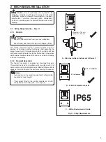
For maintenance purposes the following minimum clearances are recommended:
Left
(for receiver removal)
100 mm
Right (for emitter removal
100 mm
Top
(for cleaner removal)
200 mm
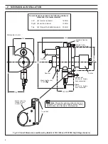
Four holes
∅
6
for mounting
Sample
inlet
(12 mm i.d. flexible
hose connection).
Drain
(12 mm i.d. flexible
hose connection)
.
Sample
outlet
,
see Fig. 2.7
for location.
Sample Outlet
Connector
for 6 mm i.d.
Tube Located
Behind the
Sensor Body
Cleaner
Receiver
Emitter
410
327
155 CRS
118
Dimensions in mm
2.3
Installing the Flowcell – Figs. 2.4 and 2.5
Notes.
•
Connecting pipework may be flexible plastic or rigid PVC, polypropylene or metal depending on the installation.
•
Isolating valves should be fitted to allow removal of the instrument.
•
Space should be left on each side of the assembly to allow access to the sensors.
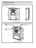
Fig. 2.4 Overall Dimensions and Mounting Details of 7320 100 (Low Range Sensor)
2
MECHANICAL INSTALLATION…