


11
Unlock and carefully remove the upper
enclosure cover.
Replace and lock secure the upper enclosure cover
Offer the cover up to the enclosure and reconnect the
ribbon cable
1
4
5
240 V
1
10 V
1
10 V
Disconnect the front panel ribbon
cable at the main p.c.b. end.
Identify the mains tappings on the 2
p.c.b's and select the required mains
voltage using the links supplied.
Note.
For 110 V both 110 V
tappings on each board MUST be
linked. Spare links for this purpose
are packed with the spare fuse.
Caution.
Support the cover during the
unlocking procedure to prevent it falling and
possibly damaging the ribbon cable and/or p.c.b.
Handbag link
3
2
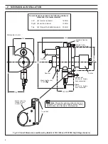
Fuses
No.
Function
Rating
1
Mains in
500 mA
2
24 V out
1 A
3
Mains in
500 mA
4
12 V out
1 A
5
Mains in
500 mA
1
2
3
4
Fuse no. 5 (see Fig. 3.3)
The cover may be
supported using the
earth cable.
3
ELECTRICAL CONNECTIONS
3.3.3
Out of Service Alarm
This alarm can be remotely transmitted via an internal relay
provided. This is a fail-safe relay which is de-energised in the
event of a diagnostics alarm – see Section 6.3.1 for details.
3.4
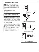
Selecting the Mains Voltage – Fig. 3.4
3.5
Start Up
When all sample/drain connections have been made and
electrical/signalling installation has been completed and
checked, switch on the power supply.
Proceed to Section 5 for programming details.
Fig. 3.4 Selecting the Mains Voltage
3.3.1
Out of Sample Alarm Input Connections
A digital input is supplied which can be connected to a low flow
indicator or sump level switch. This can be used to give
indication of the loss of the sample flow or an unacceptable
drop in water level. The input is linked to the internal system
relay when selected in the program.
The input can be configured in the software to accept an input
from a device which has normally open or closed contacts –
see Section 5.5.
If this input is not required, leave it open circuit.
3.3.2
Alarm Relay Connections
Up to two alarm relays can be provided with connections to the
single set of contacts for each alarm – see
Fig. 3.3
. Alarms can
be connected using suitable signal cable.
The operating sense of the relays can be changed using the
service programs – see
Section 5.6, Set Up Outputs
. This
enables normally open or normally closed configurations.