Device description
Connections
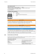
Pin allocation serial interface DTE (RJ-45)
RS-232-D
Pin
Signal V.24
Signal V.28
Direction
1
DSR M1
107
output
2
DCD M5
109
output
3
DTR S1
108.2
input
4
-
5
RxD C2
104
output
6
TxD D1
103
input
7
CTS M2
106
output
8
1
8
105
input
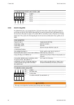
4.5.3
Interface to transmission line (X3)
In two-wire mode X3-1 and X3-2 form terminal NF1 which is used for transmission and
reception.
In four-wire mode X3-1 and X3-2 form the transmitter terminal NF1 and X3-3 and X3-4 form
the receiver pair NF2.
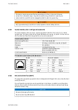
Interface to transmission line (X3)
Electrical specification
Circuit classification
ES2 (acc. IEC 62368-1)
Plug type
Phoenix Contact MSTBT 2,5/4-ST
Galvanic isolation
3 kV isolation voltage
Overvoltage protection
line to earth ±4 kV, line to line ±2 kV
Electrical fast transient / Burst, IEC
61000-4-4 4 kV (level 4), criterion A
Surge 1.2/50 µs, IEC
61000-4-5
4 kV line to earth, 2 kV line to line (level 4), cri-
terion B
Surge 10/700 µs, IEC
61000-4-5
2 kV line to earth, 1 kV line to line (level 3), cri-
terion B
Conducted disturbances, induced by radio-
frequency fields, IEC
61000-4-6
10 V (level 3), criterion A
Conducted, common mode disturbances
in the frequency range 0 Hz to 150 kHz,
61000-4-16
30 V continuous disturbance/ 300 V short
duration disturbance (level 4), criterion A
NF terminals
Transmit
Receive
2-wire
NF1: X3-1 and X3-2
NF1: X3-1 and X3-2
4-wire
NF1: X3-1 and X3-2
NF2: X3-3 and X3-4
1KGT151042
V000 1
25
Содержание 500FSD10
Страница 6: ...References Introduction 6 1KGT151042 V000 1 ...
Страница 16: ...Network structures System concept 16 1KGT151042 V000 1 ...
Страница 30: ...Maintenance Device description 30 1KGT151042 V000 1 ...
Страница 32: ...Glossary 32 1KGT151042 V000 1 ...
Страница 33: ...1KGT151042 V000 1 33 ...


