background image

Technical data 


68 265Dx, 

265VS 

IM/265D/V-EN-02 


Pos: 23.7 /Überschriften/1.1/2-spaltig/A - C/Betriebsgrenzwerte @ 1\mod_1148976534187_3101.doc @ 27515 


10.2  Operating limits 


Pos: 23.8 /Überschriften/1.1.1/1-spaltig/Temperaturgrenzen in °C (°F) @ 5\mod_1165391440171_3101.doc @ 50274 


10.2.1  Temperature limits in °C (°F)  


Pos: 23.9 /==== Wechsel ein- auf zweispaltig ==== @ 0\mod_1130421847171_3101.doc @ 3828 


Change from one to two columns 

Pos: 23.10 /Technische Daten / Datenblatt/Druck/Druckmessumformer/265Dx, 265Vx/Temperaturgrenzen @ 5\mod_1164184292718_3101.doc @ 49228 


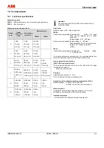
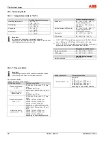
Ambient temperature range 

Operating temperature 

-40 … 85 °C 
(-40 … 185 °F) 

LCD display 

-20 … 70 °C 
(-4 … 158 °F) 

Viton seals 

-20 ... 85 °C 
(-4 ... 185 °F) 

PTFE seals 

-20 ... 85 °C 
(-4 ... 185 °F) 


Important 

In the case of applications in potentially explosive 
atmospheres, the temperature range specified on the relevant 
certificate/approval must be observed. 


Process temperature range 

Silicone oil 

-40 ... 120 °C (-40 ... 248 °F) 

1)


For operating pressures 

 10 kPa abs., 100 mbar abs., 

1.45 psia 

Carbon fluoride (265Dx only) 

-40 ... 120 °C (-40 ... 248 °F) 

2)


For operating pressures 

 atmospheric pressure 

Viton seals 
 

-20 ... 120°C (-4 ... 248 °F) 

PTFE seals 

-20 ... 85°C (-4 ... 185 °F) 


1)


 85 °C (185 °F) for operating pressures below 10 kPa, 100 mbar 

abs., 1.45 psia up to 3.5 kPa abs., 35 mbar abs., 0.5 psia 

2)


 85 °C (185 °F) for operating pressures below atmospheric 

pressure up to 40 kPa abs., 400 mbar abs., 5.8 psia 


Storage temperature range 

Storage temperature 

-50 ... 85 °C (-58 ... 185 °F) 

LCD display 

-40 ... 85 °C (-40 ... 185 °F) 


Humidity during storage 

Relative humidity 

Up to 75 % 


Pos: 23.11 /==== Wechsel zwei- auf einspaltig ==== @ 0\mod_1130421955859_3101.doc @ 3829 


Change from one to two columns 

Pos: 23.12 /==== Leeres Modul mit einer Absatzmarke, DS, 1-spaltig ==== @ 2\mod_1153381574375_0.doc @ 35553 


Pos: 23.13 /==== Leeres Modul mit einer Absatzmarke, DS, 1-spaltig ==== @ 2\mod_1153381574375_0.doc @ 35553 


Pos: 23.14 /Überschriften/1.1.1/1-spaltig/Druckgrenzen @ 5\mod_1165391594500_3101.doc @ 50295 


10.2.2  Pressure limits 


Pos: 23.15 /==== Wechsel ein- auf zweispaltig ==== @ 0\mod_1130421847171_3101.doc @ 3828 


Change from one to two columns 

Pos: 23.16 /Technische Daten / Datenblatt/Druck/Druckmessumformer/Allgemein/Grenzwerte für Einflüsse der Umgebung/Hinweis zum Prüfdruck @ 2\mod_1149584773312_3101.doc @ 28148 


Important 

When testing pressure on the pressure transmitter, please 
ensure that you observe the overpressure limits. 


Pos: 23.17 /Technische Daten / Datenblatt/Druck/Druckmessumformer/265Dx, 265Vx/Druckgrenzen @ 20\mod_1208412741687_3101.doc @ 180743 


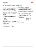
Overpressure limits 

(without damage to the transmitter) 

265Dx transmitter 

Overpressure limits 

Silicone oil for sensor 

code A 

0.5 kPa abs., 5 mbar abs., 0.07 psia 
up to 
0.6 MPa, 6 bar, 87 psi 

Carbon fluoride for 

sensor code A 

40 kPa abs., 400 mbar abs., 5.8 psia 
up to 
0.6 MPa, 6 bar, 87 psi 

Silicone oil for sensor 

code C ... R 

0.5 kPa abs., 5 mbar abs., 0.07 psia 
up to 
16 MPa, 160 bar, 2,320 psi, or 
25 MPa, 250 bar, 3,625 psi, or 
41 MPa, 410 bar, 5,945 psi 
depending on code variant selected 

Carbon fluoride for 

sensor code C ... R 

40 kPa abs., 400 mbar abs., 5.8 psia 
up to 
16 MPa, 160 bar, 2,320 psi, or 
25 MPa, 250 bar, 3,625 psi, or 
41 MPa, 410 bar, 5,945 psi 
depending on code variant selected 


265Vx transmitter 

Overpressure limits 

Sensor code F ... N 

Absolute 0 
up to 
16 MPa, 160 bar, 2,320 psi, or 
25 MPa, 250 bar, 3,625 psi, or 
41 MPa, 410 bar, 5,945 psi 
depending on code variant selected 


Содержание 265DS

Страница 1: ...ressure Transmitter 265Dx 265VS Pos 1 Titelblätter Copyright BA IA Druck Druckmessumformer Titelblatt Druckmessumformer 265D 265V 5 mod_1163755786968_3101 doc 48426 Model 265DS 265DC 265DR Model 265VS Pos 2 Seitenumbruch 0 mod_1126532365768_3101 doc 3830 ...

Страница 2: ...y Tel 49 551 905 534 Fax 49 551 905 555 CCC support deapr de abb com Copyright 2008 by ABB Automation Products GmbH Subject to changes without notice This document is protected by copyright It assists the user in safe and efficient operation of the device The contents of this document whether whole or in part may not be copied or reproduced without prior approval by the copyright holder Pos 4 Inha...

Страница 3: ...tificate Declaration of conformity 15 2 2 Explosion protection type Intrinsically safe EEx I 15 2 3 Use in areas with combustible dust 16 2 4 Category 3 for use in Zone 2 16 2 5 Explosion protection type Flameproof enclosure EEx d 17 2 6 Explosion protection types Intrinsically safe Flameproof enclosure and Limited energy equipment 18 2 7 Canadian Standards Association CSA Explosion proof 18 2 8 A...

Страница 4: ...urrent 45 8 1 2 Transmitter with PROFIBUS PA communication 46 8 1 3 Transmitter with FOUNDATION Fieldbus communication 47 8 2 Configuration types 47 8 3 Configuring the parameters without an LCD display 48 8 4 Configuration with the LCD display 50 8 4 1 Parallel shift OFFSET SHIFT 51 8 4 2 Damping DAMPING 52 8 4 3 Characteristic FUNCTION 52 8 4 4 Fieldbus address ADDRESS 52 8 5 Layout and contents...

Страница 5: ... output 71 10 5 Measuring accuracy 72 10 6 Operating influences 72 10 6 1 Operating influences 265Dx 72 10 6 2 Operating influences 265Vx 73 10 7 Technical specification 74 10 8 Mounting dimensions not design data 75 10 8 1 Differential pressure transmitter with barrel housing 75 10 8 2 Differential pressure transmitter with DIN housing 76 11 Mounting options with bracket 77 12 Maintenance Repair ...

Страница 6: ... please contact the manufacturer In addition ABB Automation Products GmbH declares that the contents of this manual are not part of any prior or existing agreements commitments or legal relationships nor are they intended to amend these All obligations of ABB Automation Products GmbH arise from the conditions of the relevant sales agreement which also contains the solely binding warranty regulatio...

Страница 7: ...tig A C Bestimmungsgemäße Verwendung 1 mod_1147675805609_3101 doc 10755 1 2 Intended use Pos 5 5 Sicherheit Druck Druckmessumformer Druckmessumformer 265Dx 265Vx Bestimmungsgemäße Verwendung 5 mod_1163757186312_3101 doc 48495 Measuring tasks Type 265Dx Differential pressure flowrate or level of gases vapors and liquids Type 265Vx Absolute pressure of gases vapors and liquids Measuring ranges Type ...

Страница 8: ...n of replacement parts are only permissible insofar as these are described in the manual Approval by ABB Automation Products GmbH must be sought for any activities beyond this scope Repairs performed by ABB authorized specialist shops are excluded from this Pos 5 10 Überschriften 1 1 1 spaltig S U Technische Grenzwerte 2 mod_1149666209312_3101 doc 28297 1 4 Technical limit values Pos 5 11 Sicherhe...

Страница 9: ...fe The appearance of either of these symbols next to the Danger warning indicates that an imminent risk is present Failure to avoid this will result in death or serious injury Warning Bodily injury The appearance of this symbol next to Warning indicates a potentially dangerous situation Failure to avoid this could result in death or serious injury Caution Minor injuries The appearance of this symb...

Страница 10: ... numbers refer to the information on the order confirmation or device data sheet 2 Options additional information on the order code 3 Device serial number factory no 4 Identification code with reference to the Pressure Equipment Directive SEP or 1G See the section Compliance with the Pressure Equipment Directive 97 23 EC 5 Auxiliary power 6 Parts that come into contact with medium 7 Lower to upper...

Страница 11: ...l Siliconöl IB 2 Fig 2 Example Additional name plate for devices with direct mount remote seals optional 1 Remote seal type 2 Meter size and nominal pressure 3 Max working pressure 4 Sealing surface form 5 Materials that come into contact with medium 6 Filling liquid in the remote seal system ID letters for filling liquid Pos 5 19 Seitenumbruch 0 mod_1126532365768_3101 doc 3830 ...

Страница 12: ...65DS6600018572 PED 1G PS 410 bar 265DS LTKA6B1 E1M1TACLH1 HART SW xx Bj Yr 20xx IP 67 10 5 30 V DC 4 20 mA Mat 1 4404 8 Hast C Buna N PN 410 2 5 2 5 bar min Span 0 025 bar P 0 410 bar abs eing adj 0 00 2500 000 mbar 0 00 100 00 MADE IN GERMANY II 1 2GD T 50 C EEx ia IIC T6 II 1 2GD T 95 C EEx ia IIC T4 ZELM 01 ATEX 0064 Electr Data see EC Type Examination Certificate TAG 0032 Fig 3 1 PED 1G 2 CE 0...

Страница 13: ...gulations for shipping purposes All devices delivered to ABB Automation Products GmbH must be free from any hazardous materials acids alkalis solvents etc Pos 5 26 Sicherheit Allgemein ungültig Entsorgung 2008 09 29 14 31 57 10 mod_1176447410937_3101 doc 81544 1 11 Disposal ABB Automation Products GmbH actively promotes environmental awareness and has an operational management system that meets th...

Страница 14: ... the measurement system according to requirements Pos 5 31 Sicherheit Druck Druckmessumformer Allgemein Sicherheitshinweise zur Inspektion und Wartung 2 mod_1151476841828_3101 doc 32114 1 14 Safety information for inspection and maintenance Warning Risk to persons There is no EMC protection or protection against accidental contact when the housing cover is open There are electric circuits within t...

Страница 15: ...of conformity forms an integral part of these operating instructions Pos 7 5 Überschriften 1 1 1 spaltig V Z Zündschutzart Eigensicher EEx i 1 mod_1147685129234_3101 doc 11181 2 2 Explosion protection type Intrinsically safe EEx I Pos 7 6 Ex technische Sicherheitshinweise Druck Druckmessumformer Allgemein Zündschutzart Eigensicher EEx i 4 mod_1162809647437_3101 doc 43924 Only intrinsically safe de...

Страница 16: ...nti stick coating be aware of the risk of electrostatic discharge with consideration given to the medium and transport speed Pos 7 10 Überschriften 1 1 1 spaltig J L Kategorie 3 für den Einsatz in Zone 2 3 mod_1157964061000_3101 doc 41113 2 4 Category 3 for use in Zone 2 Pos 7 11 Ex technische Sicherheitshinweise Druck Druckmessumformer Allgemein Kategorie 3 für den Einsatz in Zone 2 3 mod_1157963...

Страница 17: ...18 1994 Section 11 9 Cable and wire entries as well as plugs which do not comply with the points stipulated above may not be used To align the transmitter at the measuring point by turning by a maximum of 360 the rotatable housing may be loosened on the shaft between the measuring equipment and housing 1 Loosen the locking screw by a maximum of 1 rotation 2 Align the housing 3 Retighten the lockin...

Страница 18: ...on may not be changed If a supply is not intrinsically safe or the transmitter has been fed in a way that is not intrinsically safe the explosion protection type Intrinsically safe is no longer valid Caution Risk Failure to observe this information will have an adverse effect on explosion protection Appropriate cable and wire entries must be used depending on the explosion protection type selected...

Страница 19: ...t an ambient temperature Tamb of 75 C 167 F Ex tD Dust dangerous medium A21 Suitable for Zone 21 IP 66 IP 67 Protection type T85 deg C Maximum surface temperature of the transmitter at an ambient temperature Tamb of 75 C 167 F for dust layers of up to 50 mm 1 97 inch in thickness The transmitters have been certified in accordance with the following standards IEC 60079 0 2004 AS NZS 60079 0 2005 El...

Страница 20: ...d cable glands that are approved for temperatures of 80 C 176 F Openings in the housing that are not being used must be closed in accordance with the standards listed above Before switching on the operating voltage The housing must be closed Secure the housing cover by turning the locking screws hex head socket screws counterclockwise Secure the housing against rotating by turning the locking scre...

Страница 21: ...s and a write protection switch is available for local operation Important It is not possible to activate the write protection function via the control unit with the FOUNDATION Fieldbus communication type The local control unit can be used in conjunction with a built in LCD display for external configuration and parameterization of the transmitter regardless of the selected communication protocol ...

Страница 22: ...ic pressure are transferred to the measuring diaphragm of the silicon differential pressure sensor and of the absolute pressure sensor via the isolating diaphragms and filling liquid 265Vx The fully welded measuring cell is a two chamber system with an interior overload diaphragm and interior silicon absolute pressure sensor The existing absolute pressure pabs is transferred to the measuring diaph...

Страница 23: ...ply 12 Test instrument 13 Microprocessor based electronics 14 Matching electronics With HART devices the 4 20 mA output signal can be tested at the TEST terminals without interrupting the signal circuit this does not apply to fieldbus devices Use an ammeter with an internal resistance of 10 Ω for this purpose To ensure maximum possible accuracy we recommend switching the measuring device directly ...

Страница 24: ...e most important transmitter functions or data can be externally parameterized and configured using the local control unit in conjunction with the LCD display see the section Configuration M00157 1 2 3 4 5 6 7 8 9 11 12 13 14 10 Fig 5 265Vx transmitter for absolute pressure 1 Measuring cell 2 Overload diaphragm 3 Process connection 4 Filling liquid 5 pabs sensor 6 Isolating diaphragm 7 Reference v...

Страница 25: ...f the Gasket Process connection isolating diaphragm etc In addition the relevant directives regulations standards and accident prevention regulations must be observed e g VDE VDI 3512 DIN 19210 VBG Elex V etc Measurement accuracy is largely dependent on correct installation of the pressure transmitter and if applicable the associated measuring pipe s As far as possible the measuring setup should b...

Страница 26: ...ts of temporary immersion in water under standardized water pressure and temporal conditions Pos 11 7 Überschriften 1 1 1 spaltig D F Differenzdruckmessumformer 17 mod_1201094466859_3101 doc 153818 4 3 Differential pressure transmitter Pos 11 8 Montage Druck Druckmessumformer Druckmessumformer 265Dx 265Vx Differenzdruckmessumformer 17 mod_1201094621953_3101 doc 153843 The pressure transmitter can ...

Страница 27: ...ending or descending The measuring pipes should be blown through with compressed air or better yet flushed through with the measuring medium before connection Where a fluid vaporous measuring medium is being used the liquid in both measuring pipes must be at the same level If a separating liquid is being used both measuring pipes must be filled to the same level 265Dx Although it is not absolutely...

Страница 28: ...ry M20 x 1 5 or 1 2 14 NPT thread or Han 8D plug 8U PROFIBUS PA and FOUNDATION Fieldbus M12 x 1 or 7 8 plug The screw terminals are suitable for wire cross sections of up to 2 5 mm2 AWG 14 Important With Category 3 transmitters for use in Zone 2 the cable gland must be installed by the customer see the section Use in explosion proof areas An M20 x 1 5 thread is located in the electronics housing f...

Страница 29: ...e with fieldbus transmitters 6 Cable entry e g via M20 x 1 5 The electrical connection is established in the connection area The housing cover must be unscrewed for this purpose The M20 x 1 5 cable glands which are supplied by the manufacturer are screwed only loosely into the electronics housing In order to achieve protection type IP 67 the glands must be screwed in using a suitable tool hexagon ...

Страница 30: ...onnection diagram left 4 20 mA current output with HART communication protocol and power supply right PROFIBUS PA or FOUNDATION Fieldbus 1 4 20 mA 2 Non EEx area 10 5 14 45 V or EEx area 10 5 14 30 V 3 PROFIBUS PA or FOUNDATION Fieldbus 4 PROFIBUS PA Connection to PLC or PC via segment coupler linking device FOUNDATION Fieldbus Connection to PLC or PC via FF supply unit Pos 13 8 Seitenumbruch 0 mo...

Страница 31: ...nschluss über Stecker 5 mod_1164014915078_3101 doc 48790 1 2 3 4 M00039 1 2 4 3 7 8 M12 x 1 Fig 9 Fieldbus connector Important Mating plugs sockets are not included in the delivery scope Pin assignment Pin number FOUNDATION Fieldbus PROFIBUS PA 1 2 3 4 FF FF Shield Ground PA Ground PA Shield 2 1 2 M00159 3 1 Fig 10 HART Han 8D 8U plug connector 1 Barrel type 2 DIN type 3 Harting Han 8D 8U socket i...

Страница 32: ...e been stripped they are then inserted into the socket 1 from the rear 2 Slide the set screw 6 clamping ring 5 gasket 4 and housing 3 onto the cable in the order indicated before assembly you may have to adjust the gasket 4 to fit the cable diameter Important Before you press the contacts completely into the socket check the connection points again Incorrectly inserted contacts can be removed by u...

Страница 33: ...this protective circuit is used Pos 13 20 Überschriften 1 1 1 spaltig A C Aufbau des Kommunikationskreises 1 mod_1147683286828_3101 doc 11075 5 7 Communication setup Pos 13 21 Elektrischer Anschluss Druck Druckmessumformer Allgemein Aufbau des Kommunikationskreises 2 mod_1149836641921_3101 doc 28928 4 20 mA HART protocol The transmitter can be operated via a modem using a PC or laptop The modem ca...

Страница 34: ...A Pressure transmitter 2 Supply unit 1 FSK modem 2 Possible connection points for a modem between A and B M00011 RS 232C p I FSK A UB US R 2600T 4 20 mA p I FSK A UB US R 2600T 4 20 mA 1 1 3 2 2 Fig 13 Communication mode FSK bus 1 FSK bus 2 Supply module with HART isolation 3 FSK modem Pos 13 22 Seitenumbruch 0 mod_1126532365768_3101 doc 3830 ...

Страница 35: ...h The maximum line length is limited Dual core cable 3 000 m 9 842 ft Multi core cable 1 500 m 4 921 ft The actual possible line length of the electrical circuit depends on the total capacitance and resistance and can be estimated using the following formula C 10000 f C C R 6 10 65 L L Line length in meters R Total resistance in Ω ohms C Line capacitance in pF m Cf Maximum internal capacitance of ...

Страница 36: ...t be grounded The switch on behavior corresponds to Draft DIN IEC 65C 155 CDV of June 1996 If the transmitter is operated on an Ex segment coupler linking device in accordance with DIN EN 61 158 2 of October 1994 time dependent current limiting may cause the maximum number of devices to be reduced The OUT variable is transmitted cyclically This consists of the output value and 1 byte of status inf...

Страница 37: ...n the positive shut off valve To put the transmitter out of operation carry out the steps in reverse order Important In the case of the 265Vx pressure transmitter for absolute pressure with a measuring range of 400 mbar abs please be aware that the measuring equipment will have been overloaded by the atmospheric pressure due to the long periods of transport and storage involved For this reason you...

Страница 38: ...only operates with the zero reset function A current that is 4 mA or 20 mA may also indicate that the microprocessor has detected an internal error Standard setting for error detection 21 mA The graphical user interface DTM can be used to diagnose the error Important A brief interruption in the power supply results in initialization of the electronics program restarts Pos 15 6 Überschriften 1 1 1 ...

Страница 39: ...e pressure must be stable and applied with a high level of accuracy 0 05 observing the set damping value 2 Press the 0 button on the pressure transmitter The output signal is set to 4 mA The span remains unchanged Important A lower range value set using this method will be stored in the non volatile memory 25 s HART 110 s PROFIBUS PA and 15 s FOUNDATION Fieldbus when the 0 button is pressed for th...

Страница 40: ...os 15 14 Überschriften 1 1 1 spaltig M O Montage Demontage der Tasteinheit 2 mod_1149843645359_3101 doc 29159 6 5 Installing Removing the button unit Pos 15 15 Inbetriebnahme Druck Druckmessumformer Allgemein Montage Demontage der Tasteinheit 2 mod_1149843760359_3101 doc 29180 1 Slacken the screw on the protective cap and move the cap to one side 2 Using a suitable screwdriver for example push the...

Страница 41: ...ttach the LCD display Depending on the mounting position of the pressure transmitter the LCD display may be attached in four different positions This enables 90 or 180 rotations Important In the case of LCD displays with backlighting optional a 3 wire cable with a plug is located at the rear of the LCD display Connect this plug to the 3 pin terminal in the electronics area before attaching the dis...

Страница 42: ...umper or cable connector for an LCD display with backlighting 2 Jumper holder for an LCD display with backlighting 3 10 pin terminal strip for the LCD display Important The jumper item 1 must be present if the backlighting option has not been selected for the LCD display Pos 15 19 Seitenumbruch 0 mod_1126532365768_3101 doc 3830 ...

Страница 43: ...149845029468_3101 doc 29243 Each of the front faces of the electronics housing features a locking screw hex head socket screw SW 3 on the top right hand side 1 Attach the housing cover to the housing by hand tightening the screws 2 Turn the locking screw counterclockwise to secure the housing cover This involves unscrewing the screw until the screw head stops at the housing cover M00044 1 Fig 16 S...

Страница 44: ...ntrol unit on the transmitter consists of 2 buttons for external setting of the lower range value 0 and upper range value 100 parameters as well as a write protection switch Important No housing entries are required for the buttons or switch To access the buttons the screw must be slackened and the protective cap moved to one side see Fig 17 M00054 1 2 3 Fig 17 Control elements 1 Protective cap 2 ...

Страница 45: ...3101 doc 29461 Transmitters are calibrated at the factory to the customer s specified measuring range The calibrated range and tag number are provided on the name plate If this data has not been specified the transmitter will be delivered with the following configuration 8 1 1 Pressure transmitter with HART communication and 4 20 mA output current Parameters Factory settings 4 mA Zero position 20 ...

Страница 46: ...it URL Upper warning limit Upper range limit URL Lower warning limit Lower range limit LRL Lower alarm limit Lower range limit LRL Hysteresis limit value 0 5 of output scale PV filter 0 125 sec Address 126 Any or all of the configurable parameters listed above including the lower and upper range values can easily be changed using the PC operation software SMART VISION with DTM for 2600T Data regar...

Страница 47: ... can be changed using any FOUNDATION Fieldbus compatible configuration tool Data regarding flange type and material O ring materials and type of filling liquid is stored in the device Pos 19 5 Überschriften 1 1 1 spaltig J L Konfigurationsarten 0 mod_1140521210140_3101 doc 3196 8 2 Configuration types Pos 19 6 Konfiguration Parametrierung Druck Druckmessumformer Allgemein Konfigurationsarten 2 mod...

Страница 48: ...ment Make sure that the measuring limits are not exceeded Important Reducing stations with adjustable pressure and reference displays can be used as pressure transducers When making the connection please ensure that there are no residual fluids for gaseous testing materials or air bubbles for fluid testing materials in the connection lines since these can lead to errors during inspection Any poten...

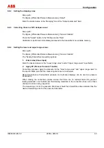
Страница 49: ...arameter will be stored in the non volatile memory 10 s after the 0 or 100 button is last pressed Warning Potential damage to parts Operating the control buttons with a magnetic screwdriver is not permitted Important This configuration procedure only changes the 4 20 mA current signal it does not affect the physical process pressure shown on the digital display or user interface To avoid potential...

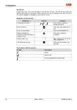
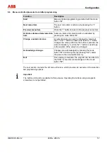
Страница 50: ...he LCD display The full menu structure can be found in the section Menu structure EXIT Exit the menu VIEW View selected measured values and calculation values GET 0 Lower range value with applied pressure GET 100 Upper range value with applied pressure SET 0 Lower range value without applied pressure SET 100 Upper range value without applied pressure SHIFTZERO Correct zero drift e g oblique sensor...

Страница 51: ...alue 6 Old end value 7 Old balance point This function can be performed at any point on the characteristic provided that the following circumstances apply The process variable is within the set measuring range The pressure transmitter has a linear transmission characteristic Entering the desired output current as a percentage performs an offset shift for the measuring range When pressure px is app...

Страница 52: ... transition point or individual values of the freely programmable characteristic cannot be changed here A handheld terminal or graphical user interface DTM must be used in order to make changes 8 4 4 Fieldbus address ADDRESS This menu item enables you to change the fieldbus slave address A number between 0 and 126 must be entered for the selected pressure transmitter All new devices receive the fa...

Страница 53: ...ighting 8 5 1 Displaying a physical value M00053 1 2 3 4 Fig 20 1 Symbol for Transmission function e g linear Mode Status code 2 Bar for displaying the process value in 3 Current measured value 1st line 4 Unit 2nd line First line In the first line the first column indicates the sign and the next six digits display the measured value amount Decimal point display The position of the decimal point is...

Страница 54: ...mbols Display for Symbol Comment Transmission function or One of these symbols is always displayed Write protection Only when write protection is set Cyclic communication Only with PROFIBUS PA Status available e g measuring range exceeded or hardware error Only when a status is available Display value code 1 9 Menu display see the section Menu structure The transmitter is busy This symbol override...

Страница 55: ...able 7th digit Bar 2 increments from 2 100 no hysteresis Pos 19 16 Überschriften 1 1 1 1 spaltig Menüstruktur 1 mod_1147935867125_3101 doc 12640 8 5 2 Menu structure Pos 19 17 Konfiguration Parametrierung Druck Druckmessumformer Druckmessumformer 265Dx 265Vx Menüstruktur Einführung 5 mod_1164102372968_3101 doc 49014 The parameters are structured in the form of a menu The menu consists of a maximum...

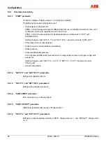
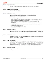
Страница 56: ...T ZERO Zero shift zero correction e g oblique sensor OFFSET SHIFT Offset shift parallel shift OUT 0 Setting for output variables OUT 100 Setting for output variables DAMPING ALARM CURRENT not with fieldbus transmitters HIGH ALARM Setting for alarm current value LOW ALARM setting for alarm current value LAST VALUE DISPLAY select LCD display value non volatile Output signal in physical unit see VIEW...

Страница 57: ...n lists are activated by pressing the mode button M Change a numerical value A numerical value can only be changed by means of the and buttons Please note that the button changes the value each time the button is pressed the value increases by 1 while the button is used to go to the position of the value to be changed Acknowledge changes Changes are acknowledged by pressing the mode button M Confi...

Страница 58: ...absolute pressure corresponds to OUT with PROFIBUS PA Setting changes under OUT 0 and OUT 100 desired unit under UNIT_OUT Percentage value of output signal Output current not with fieldbus transmitters Static pressure Pressure differential pressure Current pressure differential pressure value in range between lower and upper range limit values set Setting changes under GET 0 100 or SET 0 100 desir...

Страница 59: ...der UNIT_OUT Percentage value of output signal Output current not with fieldbus transmitters 8 6 1 10 UNIT p dp parameter Selection list of pressure units for the pressure differential pressure detected by the sensor for LCD display code no 8 under VIEW 8 6 1 11 UNIT OUT parameter Selection list of OUT units for output variables e g kg h m l h mbar for LCD display code no 1 under VIEW or DISPLAY 8...

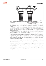
Страница 60: ... Data sheet for the SMART VISION DTM Communication protocol HART PROFIBUS PA FOUNDATION Fieldbus Hardware for HART FSK modem for PC or laptop HART handheld terminal HHT e g 691HT HHT275 375 DHH800 MFC You can use a handheld terminal to read out or configure calibrate the transmitter If a communication resistor is installed in the connected supply unit you can clamp the handheld terminal directly a...

Страница 61: ...al user interface DTM is required This DTM tool renders the device fully configurable It supports both the HART protocol and PROFIBUS PA fieldbus protocol and can be run on a PC or laptop or as part of an automation system Where FOUNDATION Fieldbus is concerned the device description DD which can be loaded onto various configuration tools is required for configuration purposes Refer to the install...

Страница 62: ...a in the transmitter automatically saves it to the non volatile memory For this purpose the transmitter must be supplied with auxiliary power for two minutes Failure to observe this will cause the transmitter to revert to the previous data the next time it is used With PROFIBUS devices local operation can only be switched off during cyclical communication If write protection is set using the DTM i...

Страница 63: ... 1 Enter value Value Input Enter the desired values in the Lower range value and or Upper range value input fields 2 Apply PV Process Pressure Transfer For setting purposes apply the pressure for the lower range value and upper range value to the device Make sure that the measuring limits are not exceeded Reducing stations with adjustable pressure and reference displays can be used as pressure tra...

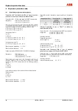
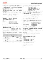
Страница 64: ...i 10 nF Effective internal inductance Li 0 Fieldbus transmitter PROFIBUS PA FOUNDATION Fieldbus Designation FISCO field device II 1 2G Ex ia IIC T6 or T4 II 1 2D Ex iaD 20 T50 C or T95 C Power supply and signal circuit with Intrinsically safe type of explosion protection only for connection to supply units certified according to the FISCO concept and with the following maximum values Ui 17 5 V Ii ...

Страница 65: ... 75 W 40 40 C 40 104 F T6 25 mA 0 5 W Fieldbus transmitter PROFIBUS PA FOUNDATION Fieldbus Intrinsically safe protection Class I II and III Division 1 Groups A B C D E F G Class I Zone 0 AEx ia Group IIC T6 T4 Non incendive Class I II and III Division 2 Groups A B C D F G Transmitter with 4 20 mA output signal HART communication and fieldbus transmitter PROFIBUS PA FOUNDATION Fieldbus Explosion pr...

Страница 66: ...e T4 40 85 C 40 185 F T5 40 50 C 40 122 F T6 40 40 C 40 104 F Supply and signal circuit for connection to supply units with the following maximum values Ex mark Characteristic Supply unit Uimax V Iimax mA Pimax W Ex ia IIC T4 T6 Rectangular or trapezoidal 17 5 360 2 52 Ex ia IIB T4 T6 Rectangular or trapezoidal 17 5 380 5 32 Ex ia IIC T4 T6 Linear 24 250 1 2 Cimax nF Limax μH 0 10 Explosion proof ...

Страница 67: ...00 bar 1 450 psi 10 000 kPa 100 bar 1 450 psi 100 kPa 1 bar 14 5 psi Important The lower range limit LRL for 265Vx is absolute 0 for all measuring ranges Span limits Maximum span URL Upper range limit 265Dx Linear freely programmable characteristic Within the range limits may be adjusted up to upper range limit Sample setting 400 400 mbar Square root characteristic Sample setting 0 400 mbar Recomm...

Страница 68: ...1130421955859_3101 doc 3829 Change from one to two columns Pos 23 12 Leeres Modul mit einer Absatzmarke DS 1 spaltig 2 mod_1153381574375_0 doc 35553 Pos 23 13 Leeres Modul mit einer Absatzmarke DS 1 spaltig 2 mod_1153381574375_0 doc 35553 Pos 23 14 Überschriften 1 1 1 1 spaltig Druckgrenzen 5 mod_1165391594500_3101 doc 50295 10 2 2 Pressure limits Pos 23 15 Wechsel ein auf zweispaltig 0 mod_113042...

Страница 69: ...columns Pos 23 20 Leeres Modul mit zwei Absatzmarken DS 1 spaltig 3 mod_1159257408468_0 doc 42813 Pos 23 21 Überschriften 1 1 2 spaltig G I Grenzwerte für Einflüsse der Umgebung 1 mod_1148983063968_3101 doc 27538 10 3 Environmental limits Pos 23 22 Wechsel ein auf zweispaltig 0 mod_1130421847171_3101 doc 3828 Change from one to two columns Pos 23 23 Technische Daten Datenblatt Druck Druckmessumfor...

Страница 70: ...ation LCD display optional 19 segment alphanumeric display two lines six characters with additional bar chart display option of backlighting for customized display of Output current in percent Output current in mA Freely selectable process variable Diagnostic messages alarms measuring range upper limit violations and changes to the configuration are also displayed Output signal 4 20 mA two wire ou...

Страница 71: ...satzmarken DS 1 spaltig 3 mod_1159257408468_0 doc 42813 Pos 23 37 Überschriften 1 1 1 1 spaltig FOUNDATION Fieldbus Ausgang 5 mod_1165392250328_3101 doc 50358 10 4 3 FOUNDATION Fieldbus output Pos 23 38 Wechsel ein auf zweispaltig 0 mod_1130421847171_3101 doc 3828 Change from one to two columns Pos 23 39 Technische Daten Datenblatt Druck Druckmessumformer 265Dx 265Vx FOUNDATION Fieldbus Ausgang 5 ...

Страница 72: ... psi 1 2 kPa 12 mbar 4 8 in H2O Pos 23 45 Wechsel zwei auf einspaltig 0 mod_1130421955859_3101 doc 3829 Change from one to two columns Pos 23 46 Leeres Modul mit einer Absatzmarke DS 1 spaltig 2 mod_1153381574375_0 doc 35553 Pos 23 47 Leeres Modul mit einer Absatzmarke DS 1 spaltig 2 mod_1153381574375_0 doc 35553 Pos 23 48 Überschriften 1 1 2 spaltig A C Betriebseinflüsse 1 mod_1148984091031_3101 ...

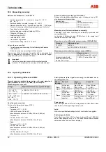
Страница 73: ...ature on the zero signal and span turndown up to 15 1 in relation to the set span Range Maximum effect on zero signal and span 10 60 C 14 140 F 0 1 x TD 0 1 40 10 C 40 14 F and 60 80 C 140 176 F 0 05 10 K x TD 0 05 10 K Power supply Within the specified limits for the voltage load the total effect is less than 0 001 of the upper range limit per volt Load Within the specified load voltage limits th...

Страница 74: ... Additional tag plate e g for marking measuring points Tag with wire both stainless steel attached to the transmitter with a maximum of 30 characters including spaces Lightning protection Up to 4 kV Voltage pulses 1 2 μs rise time 50 μs delay time at half value Current pulses 8 μs rise time 20 μs delay time at half value Not available for devices with ATEX EEx nL or PROFIBUS PA FOUNDATION fieldbus...

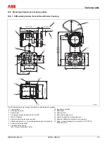
Страница 75: ... 2 28 114 4 49 23 0 91 20 0 79 71 2 80 70 2 76 26 1 02 186 7 32 108 4 25 30 1 18 90 3 54 61 2 40 M00160 1 2 3 4 9 8 7 10 13 6 5 15 16 11 12 14 Fig 23 Dimensions in mm inches deviations in the drawing are possible 1 Terminal side 10 Electrical connection 2 Housing stop screw 11 Name plate 3 Sensor plate 12 Housing cover 4 Process connection conforms to IEC 61518 13 Plate with key legend etc 5 With ...

Страница 76: ...6 3 78 139 5 47 41 3 1 63 48 1 89 27 1 06 20 0 79 1 2 3 12 4 5 6 7 8 9 10 11 13 14 11 15 Fig 24 Dimensions in mm inches deviations in the drawing are possible 1 Space for rotating the keyboard cover required 8 Housing cover 2 Additional tag plate e g for marking measuring points optional 9 Terminal side 3 Electrical connection 10 Electrical connection blind plug 4 Sensor plate 11 Space for removin...

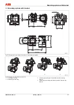
Страница 77: ...winkel 7 mod_1159171943671_3101 doc 42705 Ø 10 0 4 60 2 36 135 5 5 33 72 2 83 72 2 83 Ø 11 0 43 214 8 43 56 2 20 72 2 83 136 5 35 57 2 24 110 4 33 M00138 Fig 25 Dimensions in mm inches deviations in the drawing are possible 1 2 3 4 M00139 Fig 26 Deviations in the drawing are possible 1 Vertical pipe mounting 2 Horizontal pipe mounting 3 Vertical pipe mounting and transmitter above the mounting bra...

Страница 78: ...er or approved by a certified expert following repair work Observe the relevant safety precautions before during and after repair work Only disassemble the transmitter to the extent necessary for cleaning inspection repairs and replacement of damaged components Returns Defective transmitters sent to the repairs department must wherever possible be accompanied by your own description of the fault a...

Страница 79: ...gms are not damaged in the process 3 Use a soft brush and suitable solvent to clean the isolating diaphragms and if necessary the process flange Caution Potential damage to parts Do not use sharp or pointed tools 4 Insert the new process flange O rings in the process flange 5 Attach the process flange to the measuring cell Caution Potential damage to parts Do not damage the isolating diaphragms Th...

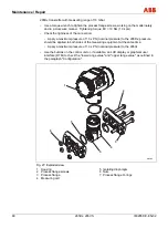
Страница 80: ...e should be applied to both sides of the measuring equipment at the same time Apply a maximum pressure of 1 0 x PN nominal pressure to the 265Vx Use the buttons on the control unit or if available an LCD display or graphical user interface DTM to check the lower range value and upper range value as outlined in the paragraph Configuration M00150 1 2 3 4 5 7 6 Fig 27 Exploded view 1 Housing 2 Proces...

Страница 81: ... cover with EEx d 2 Following this remove the LCD display if present from the electronics To do this slacken the two screws 3 Slacken the two fixing screws for the electronics and carefully remove the electronics from their housing 4 Remove both plugs from the electronics Both plugs feature mechanical polarity protection and the smaller of the two also has a mechanical locking device 5 Grasp the t...

Страница 82: ...3 23 EEC Conforms to Pressure Equipment Directive PED 97 23 EC By placing the CE mark on its devices ABB Automation Products GmbH declares that they conform to these directives Explosion protection approvals This symbol indicates devices with an explosion proof design With Ex designs if this symbol appears on an additional name plate it means that the following also applies Conformity to ATEX Dire...

Страница 83: ...Appendix IM 265D V EN 02 265Dx 265VS 83 Pos 27 6 Anhang Druck Allgemein EG Konformitätserklärung 23 mod_1226502446812_3101 doc 224503 Pos 27 7 Seitenumbruch 0 mod_1126532365768_3101 doc 3830 ...

Страница 84: ...act person Telephone Fax E mail Device details Type Serial no Reason for the return description of the defect Was this device used in conjunction with substances which pose a threat or risk to health F Yes F No If yes which type of contamination please place an X next to the applicable items Biological F Corrosive irritating F Combustible highly extremely combustible F Toxic F Explosive F Other to...

Страница 85: ...on 21 Differential pressure transmitter 26 Differential pressure transmitter with barrel housing 76 Differential pressure transmitter with DIN housing 77 Disposal 13 E Electrical connection 28 Electrical connection in the cable connection area 29 Electrical connection with plug 31 Electrical data and options 71 Environmental limits 70 Explosion protection data 65 Explosion protection type 15 17 Ex...

Страница 86: ...tion for electrical installation 14 Securing the housing cover with EEx d 44 T Technical data 68 Technical limit values 8 Technical specification 75 Temperature limits in C F 69 Transport and storage 14 Turning the housing in relation to the measuring equipment 41 Type examination certificate Declaration of conformity 15 U Use in areas with combustible dust 16 Use in explosion proof areas 15 W War...

Страница 87: ......
Страница 88: ...out notice Printed in the Fed Rep of Germany 11 2008 ABB 2008 3KXP300001R4201 IM 265D V EN 02 ABB Limited Salterbeck Trading Estate Workington Cumbria CA14 5DS UK Tel 44 0 1946 830 611 Fax 44 0 1946 832 661 ABB Inc 125 E County Line Road Warminster PA 18974 USA Tel 1 215 674 6000 Fax 1 215 674 7183 ABB Automation Products GmbH Schillerstr 72 32425 Minden Germany Tel 49 551 905 534 Fax 49 551 905 5...

Отзывы: