background image

- 14 -

PHASE 2 - TRANSMITTER INSTALLATION

Traditional (Barrel) Housing horizontal mounting with flat bracket type (option B5, this is the only bracket suitable

for units quipped with Stainless Steel housing). Mounting to vertical or horizontal pipe

Traditional (Barrel) Housing horizontal mounting with wall mounting bracket (option B3 and B4)

3.3

PROCESS CONNECTIONS

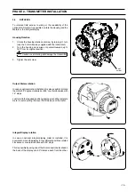
Housing Rotation

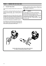
Process connections on the transmitter flange are 1/4 - 18 NPT, with a centers distance of 54mm (2.13in) between the
connections. The process connections on the transmitter flange are on centers to allow direct mounting to a three-valve or five-
valve manifold.
Flange adapter unions with 1/2 - 14 NPT connections are available as an option. Rotate one or both of the flange adapters to
attain connection centers of 51mm (2.01in), 54mm (2.13in) or 57mm (2.24in).
To install adapters, perform the following procedure:
1.

Position the adapters with the O-ring in place.

2.

Bolt the adapters to the transmitter flange using the bolts supplied.

3.

Tighten the bolts.

For model 264PS and 264VS it is only possible to have one adapter, with low pressure side flange without process connection
and drain/vent valve.

Содержание 2600T Series

Страница 1: ...1 Instruction for installation and commissioning PED 262_4D_9 FieldIT 2600T Series Pressure Transmitters Models 264B D V P...

Страница 2: ...vice and support worldwide We are committed to teamwork high quality manufacturing advanced technology and unrivalled service and support The quality accuracy and performance of the Company s products...

Страница 3: ...pressureorAbsolutepressure Themeasurementistransmitted to a control system by means of a 4 20 mA signal with a superimposed digital signal Hart or by means of a digital transmission protocols PROFIBUS...

Страница 4: ...DIAPHRAGM MATERIAL FILL FLUID check that all the parameters listed on this label or on the certificates enclosed with the transmitter are in accordance with the requirements of the area where the tran...

Страница 5: ...ng Meet ANSI ISA S 82 03 hydrostatic test requirements and SAMA PMC 27 1 Other 264Dx models using direct mount and or remote seal s are compliant to SEP Sound Engineering Practice PHASE 1 PRELIMINARY...

Страница 6: ...tion with impure substances It is recommended to use sterile gloves and that the removal of protectionbagsbedoneonlyimmediatelybeforetheinstallation Do not flush with impure fluids PHASE 1 PRELIMINARY...

Страница 7: ...pplications 3 1 TRANSMITTER LOCATION Flow gate valves filling tees vent valve 3 valve manifold Flow measurement with clean liquids or steam condensable vapor 1 Place taps to the side of the line 2 Mou...

Страница 8: ...he top or side of the line 2 Mount the transmitter above the taps Level measurement with open tanks 1 Mount the transmitter at the same height or below the lowest level to be measured 2 Connect the H...

Страница 9: ...tank above the maximum level of the tank Condensate trap optional Filling tee Level measurement with closed tanks and condensable fluids wet leg 1 Mount the transmitter at the same height or below th...

Страница 10: ...ion of the process tap 3 Connect the H side of the transmitter to the tank gate valve Dirty fluids Pressure or absolute pressure measurement of a liquid in a pipe 1 Place the tap at the side of the li...

Страница 11: ...de of the transmitter to the pipe 4 Fill the vertical section of the connecting line to the tap with a compatible liquid through the dedicated filling tee gate valve Pressure or absolute pressure meas...

Страница 12: ...ent valves so that process fluid is directed down and away from technicians when the valvesareused Thiscanbeaccomplishedbypointingthehole in the outside valve body downward and away PHASE 2 TRANSMITTE...

Страница 13: ...ITTER INSTALLATION Traditional Barrel housing vertical mounting with bracket for vertical or horizontal pipe option B1 and B2 DIN housing vertical mounting with bracket for vertical or horizontal pipe...

Страница 14: ...en the connections The process connections on the transmitter flange are on centers to allow direct mounting to a three valve or five valve manifold Flange adapter unions with 1 2 14 NPT connections a...

Страница 15: ...ill damage the transmitter 3 Tighter the set screw Output Meters rotation In case an optional meter is installed it is also possible to rotate the meter 90 degree clockwise or 255 counterclockwise wit...

Страница 16: ...ed to a lower value WARNING Electrical shock can result in death or serious injury Avoid contact with the leads and terminals High voltage that may be present on leads can cause electrical shock Follo...

Страница 17: ...r rotation by turning the set nut use the 2mm Allen key supplied with the instrument IncaseofFForProfibusconnectionsseetherelevantdiagram For further information find the relevant instruction manuals...

Страница 18: ...pressure A valve to admit process fluid to both sides of primary 2 Vent or drain primary as follows a Liquid service Vent all entrapped air from both sides of primary using vent drain valves then clos...

Страница 19: ...rain valves on the transmitter then close them 2 Make sure to have the level in the tank at the required reference minimum level Note In case it is not possible to empty the tank it is possible to fol...

Страница 20: ...t leg completely filled in 5 The output should be 4 mA dc If not a Rotate the nameplate to get access to the external push buttons Gate valve Filling tee Vent drain valve b Push the zero Z button on t...

Страница 21: ...21...

Страница 22: ...22...

Страница 23: ...olved oxygen transmitters and sensors ammonia nitrate phosphate silica sodium chloride fluoride dissolved oxygen and hydrazine analyzers Zirconia oxygen analyzers katharometers hydrogen purity and pur...

Страница 24: ...6000 Fax 1 215 674 7183 ABB S p A Via Statale 113 22016 Lenno CO Italy Tel 39 0344 58111 Fax 39 0344 56278 ABB has Sales Customer Support expertise in over 100 countries worldwide www abb com instrum...

Отзывы: