6
Class I Zone 0, Class I Zone 1, Class I Zone 2, Class II Division 1, Class II Division 2, Class III Division 1, Class
III Division 2. Refer to http://en.wikipedia.org/wiki/Electrical_equipment_in_hazardous_areas
Warning: Do not use this unit near sparks, open flames or other possible sources of ignition.
OPERATING THE UNIT
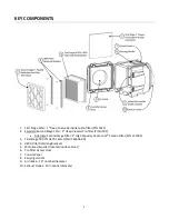
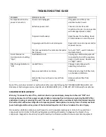
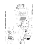
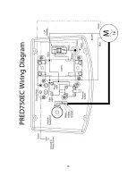
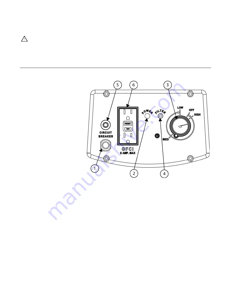
IDENTIFYING KEY COMPONENTS OF THE CONTROL PANEL
1.
Power Cord - Hardwired, 14/3
AWG SJTW power cord for
connection to electrical outlet.
2.
Power Indicator - Green light
that indicates speed control
switch is “ON” and system is
connected to power source.
3.
Speed Control Switch - Serves
as the power switch and
provides a variable adjustment
to the speed of the motorized
impeller.
4.
Filter Change Indicator – Red
light that indicates excessive
restriction on intake or loading
of the filter(s) and that filter
change procedures should be
followed. Check the Filter
Change Indicator when the unit
is operating at “HIGH” speed.
5.
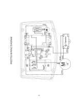
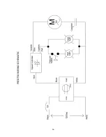
Circuit Breaker - 12 amp circuit breaker that provides protection for the unit’s electrical components.
6.
GFCI Receptacle - Electrical safety device that will trip and stop the flow of electricity if leakage of current is
detected from the unit or an electrical device plugged into the GFCI receptacle. The PRED750/PRED750EC
can supply a total of 8 amps of electrical power for additional equipment that is connected to the GFCI
receptacle. Do not exceed this 8 amp limit. Note: If the equipment connected to the GFCI receptacle draws
more than a total of 8 amps, the circuit breaker on the control panel and/or the building breaker will trip.
This condition can be remedied only by reducing the total amperage draw.
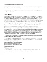
BEFORE OPERATING THE UNIT, NOTE THE FOLLOWING:
Inspect and tighten any HEPA filter retaining nuts that may have loosened during transportation. Inspect the
filters for any material or structural damage prior to use and replace any damaged filters before operating the
unit. When removing any filters prior to operation, always put them back in place with airflow indicator on filter
housing oriented in the proper direction (if applicable).
Be sure to remove the foam plug from the inlet before use. Keep this foam plug so that the inlet can be plugged
again after use to contain any debris that has been captured in the machine.


