background image

12 

2.6 Connect Redundant Power Supply (Optional) 
 

WARNING 

 
Do NOT turn on power  switch before  connecting  to  the  In-Band 
Management Chassis.  Inappropriate operation  may  cause  system damage 
or possibly injure personnel. 


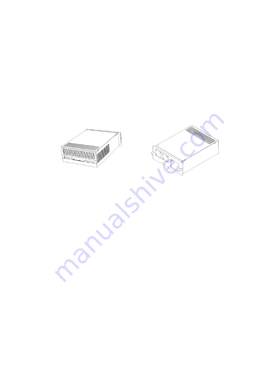
Front View 


Rear View 


NOTE


1.  Redundant Power Supply is hot swappable 
2.  Redundant Power Supply is active and concurrent with internal power  

supply 

3.  Please refer to the User’s Guide that comes with the FCM Redundant 

Power Supply for cabling specifications and detailed connection 
procedures 


2.7 Power On the In-Band Management Chassis 

 
Procedure 


1.  Check the power outlet 
2.  Connect the power cord to the power outlet 
3.  Turn on the In-Band Management Chassis 
4.  Verify the In-Band Management Chassis status 

-

  Power A is on 

-


FAN is Spinning


Содержание FCM-CHS2 Series

Страница 1: ...FCM CHS2 XX 16 SLOT IN BAND MANAGEMENT CHASSIS User s Guide Version 1 5 ...

Страница 2: ...ne or more of the following measures Reorient or relocate the receiving antenna Increase the separation between the equipment and receiver Connect the equipment into a different outlet from that the receiver is connected Consult your local distributors or an experienced radio TV technician for help Shielded interface cables must be used in order to comply with emission limits Changes or modificati...

Страница 3: ...assis 9 2 3 Install slide in modules 10 2 4 Install the In Band Management Chassis 11 2 5 Connect slide in modules to network 11 2 6 Connect redundant power supply Optional 12 2 7 Power on the In Band Management Chassis 12 3 OPERATION 3 1 LED status 13 3 2 Console management 13 3 3 SNMP 13 4 MAINTENANCE 14 4 1 Fault identification 14 4 2 Hardware replacement procedures 15 4 3 Firmware upgrade 15 A...

Страница 4: ...ule via SNMP The In Band Management Chassis supports power redundancy by using a second power supply Key Features Compact size high density 19 inch rack mountable Up to 16 slide in converter modules Hot swappable converter modules and power supplies Chassis Power FAN monitoring Local module monitoring Model Media Link Speed Duplex Activity Auto Power State Remote module monitoring Model Media Link...

Страница 5: ...erface RFC 1213 1573 Private MIB CHASSIS2 RMON MIB RFC 1757 SNMP trap support Warm Cold start Authentication Fail Local Remote Link Up Down Power Fan Fail Remote Power Fail Local Module Install Remove Plug and play operation LED indication Power PRI SEC ACT LAN COM Optional redundant power supply Support 2 hot swappable power modules AC100 240V or DC48V ...

Страница 6: ...P to monitor the system and installed slide in module status The In Band Management Chassis can be monitored locally through the DB 9 console port or remotely through the RJ 45 10 100Base T LAN port on the Management Module NOTE Please refer to the In Band Management Chassis Network Management Manual for detailed management functions ...

Страница 7: ...on 2 6 for Redundant Power Supply installation 1 4 Connectors Indicators and Switches Front Panel LED Power A Power A status Power B Power B status LAN 10 100Base T activity status COM Console port activity status LAN Fully compliant with 802 310 100Base T RJ 45 STP UTP connector For SNMP application COM DB 9 DTE connector Console operation For local management Management Module 16 slots for slide...

Страница 8: ...turn on when Power Supply B is active Connector AC power connection 100 240V 50 60Hz 150W External Redundant Power Supply Connector Connector Redundant power supply connection SEC LED should turn on when connected SEC ACT LED should turn on when active FAN Air ventilation Spins after powered on Fans Power Supply B Optional Power Supply A ...

Страница 9: ...as follows Environmental conditions One power outlet for the In Band Management Chassis internal power supply One power outlet for a Redundant Power Supply if ordered Proper ventilation UTP cables should not run in the same duct as the power and phone line cables Required fiber conversion slide in modules Required Fiber and UTP cables Redundant Power Supply optional Rack mounting tools 2 2 Unpacki...

Страница 10: ...ule slot position All slots are identical Slide in module can be installed into any slot 2 Remove the protective plate from selected installation slot 3 Insert slide in module carefully into the selected slot Make sure that the slide in module is firmly connected with the back plane connector 4 Screw in modules 5 Repeat steps 2 to 4 for all Slide in modules Power Modules Media Conversion Center E ...

Страница 11: ...rack position 2 Attach the mounting bracket into the In Band Management Chassis 3 Align the In Band Management Chassis with mounting brackets into the selected mounting rail position 4 Fix the In Band Management Chassis with mounting brackets into the selected mounting rails position carefully and firmly Desk Top Installation 1 Plan the In Band Management Chassis desk top position 2 Place the In B...

Страница 12: ...swappable 2 Redundant Power Supply is active and concurrent with internal power supply 3 Please refer to the User s Guide that comes with the FCM Redundant Power Supply for cabling specifications and detailed connection procedures 2 7 Power On the In Band Management Chassis Procedure 1 Check the power outlet 2 Connect the power cord to the power outlet 3 Turn on the In Band Management Chassis 4 Ve...

Страница 13: ...primary power has failed Power B Turns green when redundant power is on Turns orange when redundant power has failed LAN Turns on when 10 100Base T link is up Blinks when network is active COM Turns on when console port is connected Slide In Modules LED Please refer to the User s Guide that comes with the slide in modules for LED indications 3 2 Console Management Please refer to the In Band Manag...

Страница 14: ...s Check system setup and configuration through console Whole System Not Functioning 1 Check Power LED status 2 Check Power connection 3 Reset the In Band Management Chassis power Certain Network Link Not Functioning 1 Locate related slide in module 2 Check slide in module s connection with back plane 3 Check slide in module s Power LED status 4 Check slide in module s Link LED status 5 Check UTP c...

Страница 15: ... ANY CIRCUMSTANCES open and attempt to repair it yourself Failure to observe this warning could result in serious injury or death from electrical shock Failure to observe the above warning will immediately VOID any Warranty Replace FCM Slide In Module Procedure 1 Remove the existing FCM slide in module 2 Insert new FCM slide in module carefully into the slot Make sure that the FCM slide in module ...

Страница 16: ...slide in modules Dimensions 440 mm W 395 mm D 88 mm H Shipping Weight 9 0 Kg without power supply Power AC 100 240V DC48V Consumption DC power x 1 63W AC power x 1 55W Power Full Module Consumption DC power x 1 20W AC power x 1 16W Power Without Module Temperature Operation 0 50 C Storage 20 60 C Humidity 5 90 non condensing Safety Standards CE FCC Part 15 Class A For updated specifications please...

Отзывы: