background image

This 

Safety Operating Procedure

 does not necessarily cover all possible hazards associated with the machine and should be used in conjunction with 

other references

.  It is designed to be used as an adjunct to the operation in the safety procedures and to act as a reminder to the operatior prior to 

machine use.

SAFETY OPERATING PROCEDURES 
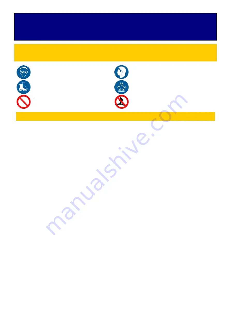
Vehicle Hoist 

DO NOT


use this machine unless the operator has been 

thoroughly instructed in its safe use and operation. 

Safety glasses must be worn at all 
times in work areas.


Long and loose hair must be 
contained.


Sturdy footwear must be worn at all 
times in work areas.


Close fitting/protective clothing must 
be worn.


Rings and jewellery must not be 

worn.


Do not stand on hoist whilst hoist is in 
operation. 

A vehicle hoist must not be operated unless it has a current certificate of inspection. 

PRE-OPERATIONAL SAFETY CHECKS 

1. Ensure that vehicle hoist has operating and maintenance instructions permanently located

and clearly visible.

2. The equipment must be used in accordance with manufacturer’s instructions.
3. Check the capacity of the hoist compared to the weight of the vehicle. If vehicle is too

heavy, do not proceed.

4. Ensure the area is clean and clear of grease, oil, and objects that may be a slip/trip hazard.
5. Familiarise yourself with and check all machine operations and controls.
6. Check all safety devices are in good condition.
7. Ensure support arms are capable of being locked in position.
8. Ensure rubber pads are in good condition on all load points.
9. Faulty equipment must not be used. Immediately report suspect equipment.

OPERATIONAL SAFETY CHECKS

1. Centre vehicle on hoist, ensuring that the weight is evenly distributed to the front and rear.
2. Identify the correct jacking points.
3. Only one person shall operate the hoist at a time.
4. Ensure hoist area is clear of people and equipment before operating.
5. Never leave the hoist running unattended.
6. Check vehicle stability by looking at the jacking points.
7. Engage and check for the correct engagement of the locks.
8. At the completion of work lower the vehicle hoist and ensure all equipment is left in a safe

position.

HOUSEKEEPING 

1. Switch off equipment.
2. Leave the equipment and work area in a safe, clean and tidy state.

POTENTIAL HAZARDS

Falling objects 

  Trapping hazards  

 Crushing 

hazards 

 Entanglement 

hazards

Содержание AutoLift PP609

Страница 1: ...TO OPERATE THIS EQUIPMENT AS DIRECTED MAY CAUSE INJURY OR DEATH Specifications subject to change without notice Note While all due care and attention has been taken in the preparation of this document...

Страница 2: ...4 1 Notice 5 4 2Layout of the equipment 6 4 3Tools for installing equipment 7 4 4Installation procedure 7 5 Introduction of control system 22 5 1 Control principle 22 5 2Control issues that need atten...

Страница 3: ...of the user manual and the operator shall be responsible for any loss or personal injury If your equipment is damaged during transportation the carrier shall be liable The equipment you purchase is s...

Страница 4: ...oose the size of the equipment L W H Ground Level 5200 2100 1900mm Second Level 5000 2050 1550mm Third level 5000 1950 1550mm Maximum weight can parking 2000kg Single equipment area 12 square meters 3...

Страница 5: ...the factory 4 1 7 When lifting or dropping the car keep away from the working area of the equipment 4 1 8 If the car on the platform is in a dangerous state there must be enough shelter space 4 1 9 Pr...

Страница 6: ...l destroy the ground which will cause damage to the equipment and casualties 4 2 4 The installation of the ground must ensure a certain level The limit cannot exceed 5 mm Within this limit it can be a...

Страница 7: ...lling equipment Hammer level open end wrench hex wrench adjustable wrench crowbar chalk or colored pen flat head screwdriver tape measure 5 m needle nosed pliers etc 4 4 Installation procedure FIG1 Do...

Страница 8: ...8 FIG2 Up position schematic...

Страница 9: ...agram 4 4 2 Move the Stage 1 and Stage 2 carriage to the distance shown in Figure 4 and support them with wooden or steel tubes of appropriate height to prevent the carriage from falling additional pl...

Страница 10: ...10 FIG4 Cariage movement diagram 4 4 3Foundation diagram FIG 5 Foundation diagram Stage 1 carriage Stage 2 carriage 500m 1000...

Страница 11: ...by the rear beam and the tie rods then install the wave plates in sequence and finally install the ramp After installation adjust the diagonals on both sides to ensure that the diagonal distance betw...

Страница 12: ...hex bolt M16 nut 16 flat pad spring washer M16 45 hex bolt M16 nut 16 flat washer spring washer Lower platfrom right beam Up platfrom right beam Lower platfrom left beam Up platform left beam Lower pl...

Страница 13: ...G 12 1 level platfrom Installation completion diagram M16X110 hex bolt M16 nut 16 flat washer spring washer bolts are worn from the outside to the inside M16X45 hex bolt M16 nut 16 flat washer spring...

Страница 14: ...14 FIG 13 2 layer plate balance shaft installation diagram FIG14 2 layer plate balance shaft installation diagram Balance axis Hexagon socket head screw M8 20 Balance sprocket...

Страница 15: ...15 FIG15 2 layer plate balance shaft installation diagram FIG16 Plate diagram Hexagon socket head screw M8 20...

Страница 16: ...16 4 4 6 Cylinder and chain installation FIG17 Cylinder Installation Diagram FIG 18 Cylinder fixing diagram Cylinder fixing bolt M8 nut Cylinder Chain clip Cylinder...

Страница 17: ...lifting sprocket guard after the chain is installed After above cylinders and other components are installed start to install chain FIG20 Chain Installation Lifting sprocket guard Lifting sprocket Cr...

Страница 18: ...18 FIG22 Chain Installation FIG23 Chain wrapping diagram Chain Clip Chain...

Страница 19: ...switch are installed This equipment has a total of 4 anti droppers and 3 limit switches 2 anti droppers are installed on the left column and 2 anti droppers and 3 limit switches are installed on the r...

Страница 20: ...G27 Lower limit installation diagram Limit switch adjustment The 1st and 2nd layer upper limits are adjusted according to the drawing requirements 1 2 layer height The lower limit position is adjusted...

Страница 21: ...Control Arm Installation diagram 4 4 9 Tubing connection connect the 1 2 with T joint connect the other side of the tube to power unit Tubing 1 L 1300mm L 4200mm Tubing 2 L 3500mm FIG 29 Tubing Conne...

Страница 22: ...urn off the power to the unit But after troubleshooting turn the button to reset it otherwise the device still can t run 5 2 Control issues that need attention 5 1 1 When assembling confirm the tightn...

Страница 23: ...hen the key switch is turned but can be lowered when rotating in the opposite direction The plate is already at the top Normal The wiring of the limit switch is in a bad condition Check the circuit of...

Страница 24: ...24 6 Electrical schematic FIG 30 7 Hydraulic schematic FIG31...

Страница 25: ......

Страница 26: ......

Страница 27: ......

Страница 28: ......

Страница 29: ......

Страница 30: ...dition by running at no load 8 1 3 Do not use the equipment if the ground or any parts are damaged 8 1 4 Do not operate the equipment if there are people or other obstacles 8 1 5 The use of equipment...

Страница 31: ...fore parking the height of all parked vehicles should not exceed the height of the platform to avoid vehicle scratches 8 3 Take cars 8 3 1 Ensure that there are no people or obstacles under the car If...

Страница 32: ...slider in the column 9 7 Common faults and repair methods Situation Possible Causes Method of exclusion When the motor is working there is no hydraulic leakage the sound is abnormal but the platform c...

Страница 33: ...m that the voltage is a stable voltage The fuse is burned Replace the fuse Running boards can not be lowered Hydraulic oil viscosity is too large Replace qualified hydraulic oil or consult local hydra...

Страница 34: ...he capacity of the hoist compared to the weight of the vehicle If vehicle is too heavy do not proceed 4 Ensure the area is clean and clear of grease oil and objects that may be a slip trip hazard 5 Fa...

Страница 35: ...ECIFIC WARRANTY PROVISIONS FOR UNITS LOCATED OUTSIDE OF THESE COUNTRIES NOTE THE EQUIPMENT IS NOT TO BE USED FOR WASH DOWN PURPOSES OR TO BE INSTALLED IN AN OUTDOOR ENVIRONMENT WHERE IT IS SUBJECT TO...

Страница 36: ...ty locks tested for correct operation Checked for good working order Supplied with the hoist and in good working order Checked for correct operation Hoist checked with load for correct operation and s...

Страница 37: ...nstrated the operation of the vehicle hoist to the owner or operator Lock off isolating switch installed Emergency stop button installed 3 Details of Electrical Contractor Trading Name Address 4 Signa...

Отзывы: