31
Temporary Drain – Evaporative
Condenser
The evaporative condenser design allows
rainwater to enter the sump tank during
transportation. AAON provides a temporary
drain system while the unit is in transit. The
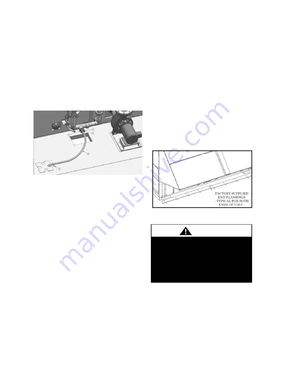
temporary drain consist of an adapter that
will connect a hose from the sump drain to
the base drain. This temporary drain must be
replaced by permanent draining piping once
on site.
Figure 12 – Temporary Drain Components
Once the unit is ready for the permanent
draining, close the valve and remove the
temporary draining system. The components
that must be removed are those with number
callouts in Figure 12. The drain connection
for the permanent draining is 2” FPT.
Access Doors
Lockable access doors are provided to the
compressor and control compartment. A
light switch is provided on the wall of the
compressor and control compartment.
A separate access door is also provided to the
evaporator
and
pumping
package
compartment. See Figure 36 for information
on leak checking these doors.
End Flashing Installation
On all LZ Series units the cabinet width will
overhang the shipping trailer on each side.
In order to secure and protect the unit during
transit the sheet metal end flashings have
been removed from the unit. The slot created
at the base of each end of the unit allows the
unit to set firmly on the trailer deck.
Sheet metal flashings are shipped loose with
the unit and once the unit is set into place the
flashings must be installed on each end of the
unit to complete the finished seal at the base.
The flashings are unit specific and designed
to cover the slot at each end of the unit to
prevent water run-off into the curb.
Failure to attach and seal the end of unit with
the flashings may result in water leakage into
the curb.
Figure 13 - Factory Supplied End Flashings
In order to prevent water leakage into
the roof curb, the factory provided
sheet metal flashings MUST BE
attached to the unit base to cover the
shipping slots at both ends of the unit.
CAUTION
Содержание LZ Series
Страница 2: ......
Страница 27: ...27 Figure 6 Concrete Pad Mounting with Dimensions Figure 7 LZ Base ...
Страница 36: ...36 Figure 17 Typical Flue Vent Piping ...
Страница 40: ...40 Figure 24 Typical Vertical Vent Piping Figure 25 Vertical Termination of Air Intake and Vent Piping ...
Страница 83: ...83 ...
Страница 84: ...84 ...
Страница 95: ...95 Flo Trex Cross Section ...


