AD4412-CW
7
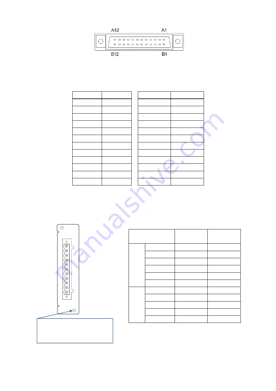
Fig. 5
Terminal numbers of control I/O connector
Fig 1
OP-02 connector terminal
Table 2
Correspondence table of control I/O and DI/DO
* Optional OP-02 Relay output and OP-05 parallel I/O can be installed in the indicator for a total of up to two units.
However, corresponding numbers for the DI/DO vary depending on the slot installed to.
Installing the OP-02 Relay output into optional slot 1 allows use of DO12 to DO20. Installing the OP-02 Relay output into
optional slot 2 allows use of DO28 to DO36. (Refer to “11.5. OP - 02
Relay output” in the instruction manual for details.)
Table 3
Correspondence table of OP-02 and DO
Input terminal DI number
Output terminal DO number
A1
DI 1
B1
DO 1
A2
DI 2
B2
DO 2
A3
DI 3
B3
DO 3
A4
DI 4
B4
DO 4
A5
DI 5
B5
DO 5
A6
DI 6
B6
DO 6
A7
DI 7
B7
DO 7
A8
DI 8
B8
DO 8
A9
DI 9
B9
DO 9
A10
DI 10
B10
DO 10
A11
DI 11
B11
DO 11
A12
(
input common
)
B12
(
output common
)
Output terminal
DO number
( optional slot 1)
DO number
( optional slot 2)
1
c
h
1
DO 12
DO 28
2
DO 13
DO 29
3
DO 14
DO 30
4
DO 15
DO 31
5
DO 16
DO 32
6
(
output common
)
(
output common
)
2
c
h
7
DO 17
DO 33
8
DO 18
DO 34
9
DO 19
DO 35
10
DO 20
DO 36
11
(
output common
)
(
output common
)
OP-02
2c
h
1
ch
Screw hole
When installing the OP-02 to the
indicator, be sure that the screws are
firmly tightened.


