25
RotoClone
®
W
© 2015 American Air Filter Company, Inc. Any use of the text or images
this document contains, without permission of American Air Filter
Company, Inc., is prohibited. RotoClone, AAF, REDClean, REDFiltration,
and Reliable Efficient Durable are registered trademarks of American Air
Filter Company, Inc. d/b/a AAF International.
9.2.4
Drive
RotoClone W units are belt-driven. Motor, if supplied by others, should be
equipped with adjustable slide base. Short center V-belt drives, if provided by
others, are the preferred arrangement. V-belt drives are usually mounted by the
factory in an Arrangement 9 motor mounting. Where the motor mounting is
Arrangement 1 or the motor and drive are too large to be shipped mounted on the
unit, refer to belt manufacturer’s recommendations for belt tension, or call AAF for
instructions. Improper tension will affect performance and life of the drive and
bearings.
9.2.5
Electrical Connections
9.2.5.1
Pressure Switch
A switch is supplied with the RotoClone which will stop the RotoClone motor
automatically when water supply fails or water pressure falls below 28 psi. This
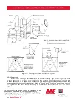
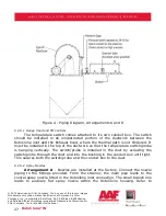
pressure switch should be mounted in the water supply line as shown in Figure 2
and wired as shown in the wiring diagram supplied with the unit. (Note: this switch
is not supplied, when “Range Hood” controls are supplied - see Section 9.2.6.1 for
Range Hood controls.)
When switch has stopped RotoClone motor because the water pressure has
dropped below 28 PSI, RotoClone cannot be started again until water pressure has
returned to not less than 30 PSI.
Switch has been adjusted at factory to operate in the range described
above. Switch setting may be checked against pressure gage reading. To readjust,
remove cover and turn adjustment screw to right or left, using pressure gage as a
guide.
9.2.5.2
FM Range Hood Controls
These controls are designed to prevent fires in kitchen range hoods beyond
the RotoClone outlet when wired according to Drawing U48P-46209 (except NY),
U48P-1427848 (NY), U48P-1653872 (Canada), or the specific wiring diagram
supplied with the unit. These controls, when supplied, include two solenoid valves,
two flow control switches (these replace the pressure switch), Fenwal Detect-A-
Fire switch, and relays. (See Section 3.8 for additional details on this option.)


