27
RotoClone
®
W
© 2015 American Air Filter Company, Inc. Any use of the text or images
this document contains, without permission of American Air Filter
Company, Inc., is prohibited. RotoClone, AAF, REDClean, REDFiltration,
and Reliable Efficient Durable are registered trademarks of American Air
Filter Company, Inc. d/b/a AAF International.
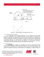
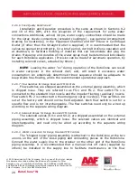
Figure 4 - Piping Diagram, Arrangements A and D
9.2.6.1
Range Hood and FM Controls
The temperature switch comes attached to its own conduit box. The switch
should be installed in an unobstructed portion of the ductwork between the
RotoClone inlet and the Exhaust hood, where the thermal path is not hindered. It
must be installed in the top of the ductwork so that the temperature switch/probe
is hanging vertically. The switch/probe is installed in the duct by screwing the
switch/probe through the duct and into the bushing in the conduit box until tight.
This secures both the switch/probe and the conduit box to the duct.
9.2.6.2
Spray Nozzles
Arrangement A
- Nozzles are installed at the factory. Connect the nozzle
piping to the fittings provided. From the strainer, the main pipe leads to the
conical spray nozzle fitted in the RotoClone inlet connection. The small branch line
leads to auxiliary flat spray nozzle within the RotoClone housing. Refer to

