P C / 1 0 4 M o d u l e
P F M - C V S
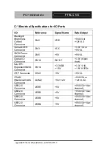
Appendix D Electrical Specifications for I/O Ports
D-6
D.4 Digital I/O Sample Program
Main()
{
aaeonSuperIOOpen();
f81866SetLdn(0x06);
// LDN6 is GPIO Configuration
Register
If(Set Digital Output High/Low?){
// Program GPIO pin to Output pin
// Example :
// GPIO8x GPIOOutputEnableRegister = 0x88
// GPIO7x GPIOOutputEnableRegister = 0x80
// 1: Set to Output Pin
// 0x0F : GPIOx0~GPIOx3 as Output Pin
f81866WriteByte(GPIOOutputEnableRegister, 0x0F);
// Set GPIO Output High/Low
// Example :
// GPIO8x GPIOOutputDataRegister = 0x89
// GPIO7x GPIOOutputDataRegister = 0x81
// 1: Output Hight, 0: Output Low
// 0x0F : GPIOx0~GPIOx3 output High
f81866WriteByte(GPIOOutputDataRegister, 0x0F);
Содержание PFM-CVS
Страница 8: ...PC 104 Module P F M C V S Chapter 1 General Information 1 1 General Chapter 1 Information...
Страница 14: ...PC 104 Module P F M C V S Chapter 2 Quick Installation Guide 2 1 Quick Installation Chapter 2 Guide...
Страница 17: ...PC 104 Module P F M C V S Solder Side Chapter 2 Quick Installation Guide 2 4...
Страница 18: ...PC 104 Module P F M C V S Chapter 2 Quick Installation Guide 2 5 2 3 Mechanical Drawing Component Side...
Страница 19: ...PC 104 Module P F M C V S Chapter 2 Quick Installation Guide 2 6 Solder Side...
Страница 46: ...PC 104 Module P F M C V S Chapter 3 AMI BIOS Setup 3 1 AMI Chapter 3 BIOS Setup...
Страница 49: ...PC 104 Module P F M C V S Setup Menu Setup submenu Main Chapter 3 AMI BIOS Setup 3 4...
Страница 50: ...PC 104 Module P F M C V S Setup submenu Advanced Chapter 3 AMI BIOS Setup 3 5...
Страница 53: ...PC 104 Module P F M C V S IDE Configuration IDE Chapter 3 AMI BIOS Setup 3 8...
Страница 56: ...PC 104 Module P F M C V S F81866 Super IO Configuration Chapter 3 AMI BIOS Setup 3 11...
Страница 57: ...PC 104 Module P F M C V S Serial Port Configuration Chapter 3 AMI BIOS Setup 3 12...
Страница 58: ...PC 104 Module P F M C V S Chapter 3 AMI BIOS Setup 3 13...
Страница 59: ...PC 104 Module P F M C V S Chapter 3 AMI BIOS Setup 3 14...
Страница 61: ...PC 104 Module P F M C V S F81866 H W Monitor Chapter 3 AMI BIOS Setup 3 16...
Страница 63: ...PC 104 Module P F M C V S Setup submenu Chipset Chapter 3 AMI BIOS Setup 3 18...
Страница 64: ...PC 104 Module P F M C V S Host Bridge Chapter 3 AMI BIOS Setup 3 19...
Страница 65: ...PC 104 Module P F M C V S Graphics Configuration Chapter 3 AMI BIOS Setup 3 20...
Страница 69: ...PC 104 Module P F M C V S BBS Priorities Chapter 3 AMI BIOS Setup 3 24...
Страница 72: ...PC 104 Module P F M C V S Chapter 3 AMI BIOS Setup 3 27 Setup submenu Exit...
Страница 73: ...PC 104 Module P F M C V S Chapter 4 Driver Installation 4 1 Driver Chapter 4 Installation...
Страница 78: ...PC 104 Module P F M C V S Chapter 4 Driver Installation 4 6 2 Restart the operating system...
Страница 91: ...PC 104 Module P F M C V S Appendix B I O Information B 1 I O Information Appendix B...
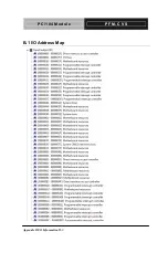
Страница 92: ...PC 104 Module P F M C V S Appendix B I O Information B 2 B 1 I O Address Map...
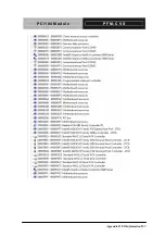
Страница 93: ...PC 104 Module P F M C V S Appendix B I O Information B 3...
Страница 94: ...PC 104 Module P F M C V S Appendix B I O Information B 4 B 2 1st MB Memory Address Map...
Страница 95: ...PC 104 Module P F M C V S Appendix B I O Information B 5 B 3 IRQ Mapping Chart...
Страница 96: ...PC 104 Module P F M C V S Appendix B I O Information B 6...
Страница 97: ...PC 104 Module P F M C V S Appendix B I O Information B 7 B 4 DMA Channel Assignments...
Страница 98: ...PC 104 Module P F M C V S Appendix C Mating Connector C 1 Appendix C Mating Connector...

