P C / 1 0 4 M o d u l e
P F M - C V S
Appendix D Electrical Specifications for I/O Ports
D-2
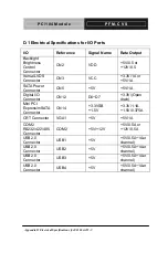
D.1 Electrical Specifications for I/O Ports
I/O Reference
Signal
Name Rate
Output
Backlight
Brightness
Control
Connector
CN2 VDD
+5V/0.5 or
+12V/0.5
Iternal LVDS
Connector
CN3 VCC
+3.3V/1A or
+5V/1A
SATA Power
Connector
CN5 +5V +5V/1A
Digital I/O
Connector
CN12 D0~D7
+3.3V/(Open
drain)
Mini PCI
Express/mSATA
Connector
CN14
+3.3VSB
+1.5V
+3.3V/1.1A
+1.5V/0.375A
CRT Connector
VGA1
+5V
+5V/1A
COM2
RS232/422/485
Connector
COM2 +5V/+12V
+5V/0.5A or
+12V/0.5A
USB2.0
Connector
USB1 +5V
+5V/0.5A~1Aer
channel)
USB2.0
Connector
USB2 +5V
+5V/0.5A~1Aer
channel)
USB2.0
Connector
USB3 +5V
+5V/0.5A~1Aer
channel)
USB2.0
Connector
USB4 +5V
+5V/0.5A~1Aer
channel)
Содержание PFM-CVS
Страница 8: ...PC 104 Module P F M C V S Chapter 1 General Information 1 1 General Chapter 1 Information...
Страница 14: ...PC 104 Module P F M C V S Chapter 2 Quick Installation Guide 2 1 Quick Installation Chapter 2 Guide...
Страница 17: ...PC 104 Module P F M C V S Solder Side Chapter 2 Quick Installation Guide 2 4...
Страница 18: ...PC 104 Module P F M C V S Chapter 2 Quick Installation Guide 2 5 2 3 Mechanical Drawing Component Side...
Страница 19: ...PC 104 Module P F M C V S Chapter 2 Quick Installation Guide 2 6 Solder Side...
Страница 46: ...PC 104 Module P F M C V S Chapter 3 AMI BIOS Setup 3 1 AMI Chapter 3 BIOS Setup...
Страница 49: ...PC 104 Module P F M C V S Setup Menu Setup submenu Main Chapter 3 AMI BIOS Setup 3 4...
Страница 50: ...PC 104 Module P F M C V S Setup submenu Advanced Chapter 3 AMI BIOS Setup 3 5...
Страница 53: ...PC 104 Module P F M C V S IDE Configuration IDE Chapter 3 AMI BIOS Setup 3 8...
Страница 56: ...PC 104 Module P F M C V S F81866 Super IO Configuration Chapter 3 AMI BIOS Setup 3 11...
Страница 57: ...PC 104 Module P F M C V S Serial Port Configuration Chapter 3 AMI BIOS Setup 3 12...
Страница 58: ...PC 104 Module P F M C V S Chapter 3 AMI BIOS Setup 3 13...
Страница 59: ...PC 104 Module P F M C V S Chapter 3 AMI BIOS Setup 3 14...
Страница 61: ...PC 104 Module P F M C V S F81866 H W Monitor Chapter 3 AMI BIOS Setup 3 16...
Страница 63: ...PC 104 Module P F M C V S Setup submenu Chipset Chapter 3 AMI BIOS Setup 3 18...
Страница 64: ...PC 104 Module P F M C V S Host Bridge Chapter 3 AMI BIOS Setup 3 19...
Страница 65: ...PC 104 Module P F M C V S Graphics Configuration Chapter 3 AMI BIOS Setup 3 20...
Страница 69: ...PC 104 Module P F M C V S BBS Priorities Chapter 3 AMI BIOS Setup 3 24...
Страница 72: ...PC 104 Module P F M C V S Chapter 3 AMI BIOS Setup 3 27 Setup submenu Exit...
Страница 73: ...PC 104 Module P F M C V S Chapter 4 Driver Installation 4 1 Driver Chapter 4 Installation...
Страница 78: ...PC 104 Module P F M C V S Chapter 4 Driver Installation 4 6 2 Restart the operating system...
Страница 91: ...PC 104 Module P F M C V S Appendix B I O Information B 1 I O Information Appendix B...
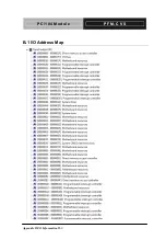
Страница 92: ...PC 104 Module P F M C V S Appendix B I O Information B 2 B 1 I O Address Map...
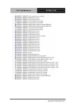
Страница 93: ...PC 104 Module P F M C V S Appendix B I O Information B 3...
Страница 94: ...PC 104 Module P F M C V S Appendix B I O Information B 4 B 2 1st MB Memory Address Map...
Страница 95: ...PC 104 Module P F M C V S Appendix B I O Information B 5 B 3 IRQ Mapping Chart...
Страница 96: ...PC 104 Module P F M C V S Appendix B I O Information B 6...
Страница 97: ...PC 104 Module P F M C V S Appendix B I O Information B 7 B 4 DMA Channel Assignments...
Страница 98: ...PC 104 Module P F M C V S Appendix C Mating Connector C 1 Appendix C Mating Connector...


