Chapter 2 Installation 19
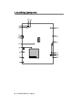
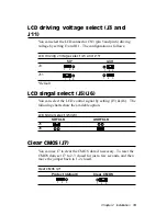
LCD driving voltage select (J3 and
J11)
You can select the LCD connector CN3 (pin 5 and pin 6) driving
voltage by setting J3 and J11. The configuration as follows:
LCD driving voltage select (J3 and J11)
5V*
3.3V
J3
J11
*default
LCD singal select (J5)(J6)
You can select the LCD control signal by setting (J5) & (J6). The
following charts show the available option.
LCD Signal select (J5)(J6)
SHF CLK
ASHF CLK
J5
J6
Clear CMOS (J7)
You can use J7 to clear the CMOS data if necessary. To reset the
CMOS data, set J7 to 2-3 closed for just a few seconds, and then
move the jumper back to 1-2 closed.
Clear CMOS (J7)
Protect (default)
Clear CMOS
1 2 3
1 2 3
1 2 3
1 2 3
1 2 3
1 2 3
Содержание PCM-5892
Страница 1: ...PCM 5894 PCM 5892 All in One Single Board Pentium Computer with SVGA Ethernet and 4 serial ports...
Страница 10: ......
Страница 18: ...8 PCM 5894 5892 User Manual...
Страница 56: ...46 PCM 5894 5892 User Manual...
Страница 100: ...9 0 PCM 5894 5892 User Manual...
Страница 114: ...104 PCM 5894 5892 User Manual...
Страница 119: ...Appendix C Optional Extras 109 C Optional Extras A P P E N D I X...

