background image

E P I C   B o a r d  

E P I C - Q M 5 7


Appendix D RAID & AHCI Settings


D

-

1


RAID  &  AHCI 

Settings 


Appendix 

Содержание EPIC-QM57

Страница 1: ...E P I C Q M 5 7 EPIC QM57 Intel Core i5 i7 Processor Supports DDR3 800 1066 Memory 24 bit Dual channel LVDS LCD 6 USB 2 0 4 COMs 2 SATA CompactFlash 8 bit Digital I O EPIC QM57 Manual Rev A 5th Ed Mar...

Страница 2: ...s manual is intended to be accurate and reliable However the original manufacturer assumes no responsibility for its use or for any in fringements upon the rights of third parties that may result from...

Страница 3: ...ash is a trademark of the Compact Flash Association z Intel Core i5 i7 are trademarks of Intel Corporation z Microsoft Windows is a registered trademark of Microsoft Corp z ITE is a trademark of Integ...

Страница 4: ...you begin installing your card please make sure that the following materials have been shipped 9657666600 Jumper Cap Product DVD EPIC QM57 If any of these items are missing or damaged please contact y...

Страница 5: ...nnectors 2 8 2 6 Setting Jumpers 2 10 2 7 PCI 104 I O Voltage Selection JP2 2 11 2 8 LCD Function Selection JP3 2 11 2 9 Clear CMOS Function JP4 2 11 2 10 Touch Screen 4 5 8 wire Mode Selection JP5 2...

Страница 6: ...8 2 26 LPT Port Connector CN20 2 19 2 27 Digital I O Connector CN21 2 20 2 28 PS2 Keyboard Mouse Connector CN23 2 21 2 29 PCIe 104 Connector CN24 2 21 2 30 RS 232 Serial Port 4 CN25 Port 3 CN26 Connec...

Страница 7: ...imer Initial Program A 6 Appendix B I O Information B 1 I O Address Map B 2 B 2 1st MB Memory Address Map B 4 B 3 IRQ Mapping Chart B 5 B 4 DMA Channel Assignments B 5 Appendix C Mating Connector C 1...

Страница 8: ...EPIC Board E P I C Q M 5 7 Chapter 1 General Information 1 1 Chapter General 1 Information...

Страница 9: ...7 chipset to achieve an excellent performance In addition EPIC QM57 deploys two Intel 82577LM and 82574L Ethernet chips to feature two RJ 45 ports onboard to display the transcendent performance of ne...

Страница 10: ...i7 Processor z Intel QM57 z SODIMM DDR3 800 1066 Memory up to 4GB 8GB optional z Gigabit Ethernet x 2 z Up To 24 bit Dual channel LVDS LCD z 2CH HD Audio z SATA2 x 2 Type 2 CompactFlash x 1 z USB2 0...

Страница 11: ...t Intel QM57 z I O Chipset ITE8781 z Ethernet 10 100 1000Base TX x 2 Intel 82577LM and Intel 82574L respectively RJ 45 x 2 z BIOS AMI Plug Play BIOS 8MB Flash z Wake On LAN Yes z Watchdog Timer Genera...

Страница 12: ...s CRT LCD simultaneous dual view displays z Chipset Intel CPU integrated VGA integrated Graphics z Memory Shared system memory up to 512 MB z Resolutions Up to 2048x1536 for CRT Up to 1920x1200 for LC...

Страница 13: ...EPIC Board E P I C Q M 5 7 Chapter 1 General Information 1 6 z Audio Line in Line out Mic in CD in...

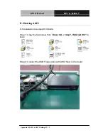
Страница 14: ...EPIC Board E P I C Q M 5 7 Chapter 2 Quick Installation Guide 2 1 Chapter Quick Installation 2 Guide...

Страница 15: ...le the power is on because a sudden rush of power can damage sensitive electronic components Always ground yourself to remove any static charge before touching the board Modern electronic devices are...

Страница 16: ...EPIC Board E P I C Q M 5 7 Chapter 2 Quick Installation Guide 2 3 2 2 Location of Connectors and Jumpers Component Side...

Страница 17: ...EPIC Board E P I C Q M 5 7 Solder Side Chapter 2 Quick Installation Guide 2 4...

Страница 18: ...EPIC Board E P I C Q M 5 7 Chapter 2 Quick Installation Guide 2 5 2 3 Mechanical Drawing Component Side...

Страница 19: ...EPIC Board E P I C Q M 5 7 Chapter 2 Quick Installation Guide 2 6 Solder Side...

Страница 20: ...uit your application The table below shows the function of each of the board s jumpers Jumpers Label Function JP2 PCI 104 I O Voltage Selection JP3 1 LCD Inverter Backlight Voltage Selection JP3 2 LVD...

Страница 21: ...CN2 LCD Inverter Backlight Connector CN3 Dual Channel LVDS LCD Connector CN5 12V DC Power Input Connector CN7 5V 12V Power Output Connector CN8 Audio Connector CN9 Touch Panel Connector CN11 RS 232 S...

Страница 22: ...CN25 RS 232 Serial Port 4 Connector CN26 RS 232 Serial Port 3 Connector CN27 External SMBUS and PS_ON Connector CN28 Fan Connector CN29 CN30 10 100 1000Base TX Ethernet Connector CN34 RS 232 422 485 S...

Страница 23: ...hem To close a jumper you connect the pins with the clip To open a jumper you remove the clip Sometimes a jumper will have three pins labeled 1 2 and 3 In this case you would connect either pins 1 and...

Страница 24: ...I O Voltage Selection JP2 JP2 Function 1 2 5V 2 3 3 3V Default 2 8 LCD Function Selection JP3 LCD Inverter Backlight Voltage Selection JP3 1 JP3 1 Function 1 3 5V Default 3 5 12V LVDS LCD Voltage Sele...

Страница 25: ...ault 4 6 Clear 2 10 Touch Panel 4 5 8 wire Mode Selection JP5 JP5 Function 1 2 Open 5 Wire 1 2 Close 4 8 Wire Default 2 11 COM2 RI 5V 12V Selection JP6 JP6 Function 1 2 12V 3 4 RI 5 6 5V Default 2 12...

Страница 26: ...12V 2 Brightness Control 3 GND 4 GND 5 Backlight Enable Note The max rating of Pin 1 is 0 5A 12V 2 15 Dual Channel LVDS LCD Connector CN3 Pin Signal Pin Signal 1 ENBKL 2 N C 3 PPVCC 4 GND 5 LVDS1_TXC...

Страница 27: ...V DC Power Input Connector CN5 Pin Signal 1 GND 2 GND 3 12V 4 12V Note Standard type is a 2 pin power connector Note Optional support DC 12V power connector 4 pin connector 2 17 5V 12V Power Output Co...

Страница 28: ...in 8 wire Signal Default 4 wire Signal 5 wire Signal 1 GND GND GND 2 Top Excite Top Excite UL Y 3 Bottom Excite Bottom Excite UR H 4 Lef Excite Lef Excite LL L 5 Right Excite Right Excite LR X 6 Top S...

Страница 29: ...8 GND 9 Lane2 N 10 Lane3 P 11 GND 12 Lane3 N 13 Config1 GND 14 Config2 GND 15 AUX CH P 16 GND 17 AUX CH N 18 Hot Plug 19 Return PWR GND 20 DP_PWR 2 22 UIM Connector CN13 Pin Signal 1 UIM_PWR 2 UIM_RS...

Страница 30: ...43 GND 44 LED_WLAN 41 3 3Vaux 42 LED_WWAN 39 3 3Vaux 40 GND 37 GND 38 USB_D 35 GND 36 USB_D 33 PETp0 34 GND 31 PETn0 32 SMB_DATA 29 GND 30 SMB_CLK 27 GND 28 1 5V 25 PERp0 26 GND 23 PERn0 24 3 3Vaux 2...

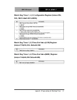
Страница 31: ...EPIC Board E P I C Q M 5 7 Chapter 2 Quick Installation Guide 2 18 1 WAKE 2 3 3Vaux...

Страница 32: ...6 INIT 7 DATA2 8 SLIN 9 DATA3 10 GND 11 DATA4 12 GND 13 DATA5 14 GND 15 DATA6 16 GND 17 DATA7 18 GND 19 ACK 20 GND 21 BUSY 22 GND 23 PE 24 GND 25 SELECT 26 N C 2 26 Digital I O Connector CN21 Pin Sign...

Страница 33: ...PIO Set 3 Bit 6 U50 Pin 12 GPIO 36 Port 4 A40h CN16 Pin 4 GPIO Set 1 Bit 4 U50 Pin 31 GPIO 14 Port 3 A40h CN16 Pin 3 GPIO Set 1 Bit 3 U50 Pin 32 GPIO 13 Port 2 A40h CN16 Pin 2 GPIO Set 1 Bit 2 U50 Pin...

Страница 34: ...6 5VA 2 30 FAN Connector CN28 Pin Signal 1 GND 2 12V Default or 5V 3 Speed Sense 2 31 RS 232 422 485 Serial Port 2 Connector CN34 Pin Signal Pin Signal 1 DCD2 422TXD 485DATA 2 DSR2 3 RXD2 422RXD 4 RT...

Страница 35: ...lation Guide 2 22 7 SM_DAT 8 CRT_VSYNC 9 DVI_TX1 10 DVI_TX1 11 GND 12 N C 13 N C 14 5V 15 GND 16 HPDET 17 DVI_TX0 18 DVI_TX0 19 GND 20 N C 21 N C 22 GND 23 DVI_TXCLK 24 DVI_TXCLK 25 GND 27 N C C1 RED...

Страница 36: ...Board E P I C Q M 5 7 Chapter 2 Quick Installation Guide 2 23 Below Table for China RoHS Requirements AAEON Main Board Daughter Board Backplane Pb Hg Cd Cr VI PBB PBDE O SJ T 11363 2006 X SJ T 11363...

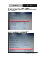
Страница 37: ...EPIC Board E P I C Q M 5 7 Chapter 3 Award BIOS Setup 3 1 Award BIOS Setup Chapter 3...

Страница 38: ...y to continue the boot up sequence System configuration verification These routines check the current system configuration against the values stored in the CMOS memory If they do not match the program...

Страница 39: ...ly This will allow you to enter Setup Standard CMOS Features Use this menu for basic system configuration Date time IDE etc Advanced BIOS Features Use this menu to set the advanced features available...

Страница 40: ...to load the BIOS default values that are factory settings for optimal performance system operations While AWARD has designated the custom BIOS to maximize performance the factory has the right to chan...

Страница 41: ...EPIC Board E P I C Q M 5 7 Chapter 4 Driver Installation 4 1 Driver Installation Chapter 4...

Страница 42: ...es that meet your needs Follow the sequence below to install the drivers Step 1 Install Chipset Driver Step 2 Install VGA Driver Step 3 Install LAN Driver Step 4 Install ME Driver Step 5 Install Audio...

Страница 43: ...u install the driver automatically Step 2 Install VGA Driver 1 Click on the Step2 VGA folder and select the OS folder your system is 2 Double click on the Setup exe in the OS folder 3 Follow the instr...

Страница 44: ...der and double click on the SETUP exe 2 Follow the instructions that the window shows 3 The system will help you install the driver automatically Step 6 Install Touch Driver 1 Click on the Step6 Touch...

Страница 45: ...EPIC Board E P I C Q M 5 7 Appendix A Programming the Watchdog Timer A 1 Programming the Watchdog Timer Appendix A...

Страница 46: ...l watchdog timer program is also attached based on which you can develop customized program to fit your application Configuring Sequence Description After the hardware reset or power on reset the ITE...

Страница 47: ...t for Key state To ensure the initial state of the key check logic it is necessary to perform four write opera tions to the Special Address port 2EH Two different enter keys are provided to select con...

Страница 48: ...Configuration Registers Configure Control Index 02h This register is write only Its values are not sticky that is to say a hardware reset will automatically clear the bits and does not require the sof...

Страница 49: ...chdog Timer A 5 Watch Dog Timer 1 2 3 Configuration Register Index 72h 82h 92h Default 001s0000b Watch Dog Timer 1 2 3 Time Out Value LSB Register Index 73h 83h 93h Default 38h Watch Dog Timer 1 2 3 T...

Страница 50: ...SMALL CODE Main CALL Enter_Configuration_mode CALL Check_Chip mov cl 7 call Set_Logic_Device time setting mov cl 10 10 Sec dec al Watch_Dog_Setting Timer setting mov al cl mov cl 73h call Superio_Set_...

Страница 51: ...l 9 call Set_Logic_Device Initial_OK CALL Exit_Configuration_mode MOV AH 4Ch INT 21h Enter_Configuration_Mode PROC NEAR MOV SI WORD PTR CS Offset Cfg_Port MOV DX 02Eh MOV CX 04h Init_1 MOV AL BYTE PTR...

Страница 52: ...Exit_Configuration_Mode ENDP Check_Chip PROC NEAR MOV AL 20h CALL Read_Configuration_Data CMP AL 87h JNE Not_Initial MOV AL 21h CALL Read_Configuration_Data CMP AL 81h JNE Not_Initial Need_Initial STC...

Страница 53: ...ation_Data ENDP Write_Configuration_Data PROC NEAR MOV DX WORD PTR CS Cfg_Port 04h OUT DX AL XCHG AL AH MOV DX WORD PTR CS Cfg_Port 06h OUT DX AL RET Write_Configuration_Data ENDP Superio_Set_Reg proc...

Страница 54: ...sh ax push cx xchg al cl mov cl 07h call Superio_Set_Reg pop cx pop ax ret Set_Logic_Device endp Select 02Eh Index Port 02Fh Data Port Cfg_Port DB 087h 001h 055h 055h DW 02Eh 02Fh END Main Note Interr...

Страница 55: ...EPIC Board E P I C Q M 5 7 Appendix B I O Information B 1 I O Information Appendix B...

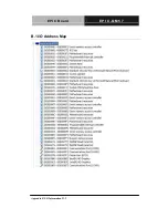
Страница 56: ...EPIC Board E P I C Q M 5 7 Appendix B I O Information B 2 B 1 I O Address Map...

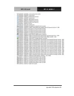
Страница 57: ...EPIC Board E P I C Q M 5 7 Appendix B I O Information B 3...

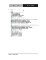
Страница 58: ...EPIC Board E P I C Q M 5 7 Appendix B I O Information B 4 B 2 1 st MB Memory Address Map...

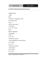
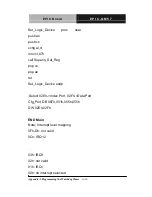
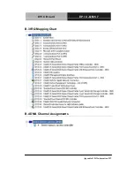
Страница 59: ...EPIC Board E P I C Q M 5 7 Appendix B I O Information B 5 B 3 IRQ Mapping Chart B 4 DMA Channel Assignments...

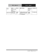
Страница 60: ...EPIC Board E P I C Q M 5 7 Appendix C Mating Connector C 1 Mating Connector Appendix C...

Страница 61: ...pins CATCH H716 or compatible N A N A CN5 Power Input Connector N A N A Big 4P Power cable 1702002010 CN7 5V 12V Power Output Connector Molex 2 0mm Pitch 4 pins Molex 87369 040X SATA Power Cable 1702...

Страница 62: ...Appendix C Mating Connector C 3 CN23 PS 2 Keyboard M ouse Connector Wafer B6B PHDSS Keyboard Mouse Cable 1700060157 CN25 26 34 COM Port Connector LIAN TAY 1 25mm pitch 9 pins LIAN TAY H752 09 or compa...

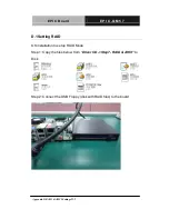
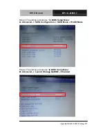
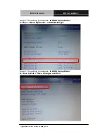
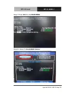
Страница 63: ...EPIC Board E P I C Q M 5 7 Appendix D RAID AHCI Settings D 1 RAID AHCI Settings Appendix D...

Страница 64: ...5 7 Appendix D RAID AHCI Settings D 2 D 1 Setting RAID OS installation to setup RAID Mode Step 1 Copy the files below from Driver CD Step7 RAID AHCI to Disk Step 2 Connect the USB Floppy disk with RA...

Страница 65: ...7 Appendix D RAID AHCI Settings D 3 Step 3 The setting procedures In BIOS Setup Menu A Advanced SATA Configuration SATA Mode RAID Mode Step 4 The setting procedures In BIOS Setup Menu B Advanced Laun...

Страница 66: ...P I C Q M 5 7 Appendix D RAID AHCI Settings D 4 Step 5 The setting procedures In BIOS Setup Menu C Boot Boot Option 1 DVD ROM Type Step 6 The setting procedures In BIOS Setup Menu D Save Exit Save Cha...

Страница 67: ...EPIC Board E P I C Q M 5 7 Appendix D RAID AHCI Settings D 5 Step 7 Press Ctrl I to enter MAIN MENU Step 8 Choose 1 Create RAID Volume...

Страница 68: ...EPIC Board E P I C Q M 5 7 Appendix D RAID AHCI Settings D 6 Step 9 RAID Level RAID0 Stripe Step 10 Choose Create Volume...

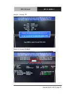
Страница 69: ...EPIC Board E P I C Q M 5 7 Appendix D RAID AHCI Settings D 7 Step 11 Choose Y Step 12 Choose 5 Exit...

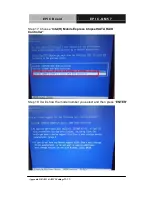
Страница 70: ...EPIC Board E P I C Q M 5 7 Appendix D RAID AHCI Settings D 8 Step 13 Choose Y Step 14 Setup OS...

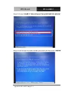
Страница 71: ...EPIC Board E P I C Q M 5 7 Appendix D RAID AHCI Settings D 9 Step 15 Press F6 Step 16 Choose S...

Страница 72: ...EPIC Board E P I C Q M 5 7 Appendix D RAID AHCI Settings D 10 Step 17 Choose Intel R Mobile Express Chipset SATA RAID Controller Step 18 It will show the model number you select and then press ENTER...

Страница 73: ...EPIC Board E P I C Q M 5 7 Appendix D RAID AHCI Settings D 11 Step 19 Setup is starting Windows...

Страница 74: ...5 7 Appendix D RAID AHCI Settings D 12 D 2 Setting AHCI OS installation to setup AHCI Mode Step 1 Copy the files below from Driver CD Step7 RAID AHCI to Disk Step 2 Connect the USB Floppy disk with A...

Страница 75: ...ndix D RAID AHCI Settings D 13 Step 3 The setting procedures In BIOS Setup Menu A Advanced SATA Configuration SATA Configuration SATA Mode AHCI Mode Step 4 The setting procedures In BIOS Setup Menu B...

Страница 76: ...EPIC Board E P I C Q M 5 7 Appendix D RAID AHCI Settings D 14 Step 5 The setting procedures In BIOS Setup Menu C Save Exit Save Changes and Exit Step 6 Setup OS...

Страница 77: ...EPIC Board E P I C Q M 5 7 Appendix D RAID AHCI Settings D 15 Step 7 Press F6 Step 8 Choose S...

Страница 78: ...EPIC Board E P I C Q M 5 7 Appendix D RAID AHCI Settings D 16 Step 9 Choose Intel R 7 Series Chipset Family SATA AHCI Controller Step 10 It will show the model number you select and then press ENTER...

Страница 79: ...EPIC Board E P I C Q M 5 7 Appendix D RAID AHCI Settings D 17 Step 11 Setup is loading files...

Отзывы: