background image

5

SR703 | SR707 CONTRACTOR AMPLIFIER

English

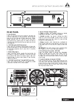
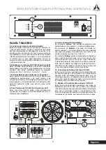
REAR PANEL

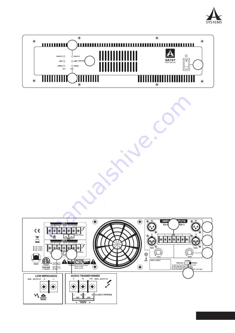
5. Gain Controls

These two knobs are the level controls for channels one 

and two respectively� Turning clockwise will increase its 

gain and counter clockwise will decrease its gain� Please 

always powerup with the volume all the way down, 

and increase the volume slowly to make sure that no 

conditions exist which could annoy your audience or harm 

your speakers�

6. CH1/CH2 Inputs (XLR Connectors)

These inputs are provided for making balanced connection 

to mixers, preamps, etc� The XLR inputs are wired as per 

the following convention: Pin 2 – Hot, Pin 3 – Cold, Pin 

1 – Ground�

7. Barrier Strip Inputs

These connection points provide the best option for 

permanent or long-term installation� Connections should 

be screwed down tight to exclude oxygen, and care 

should be taken to avoid loose strands of wire that may 

cause short circuits�

8. CH1/CH2 Parallel Pass Through XLR Connectors

These XLR output connectors are provided for parallel 

connection to another SR or other amplifier.

9. Stereo / Parallel / Bridge Switch

In 

Stereo

 operation, two separate signals are treated 

separately by channels 1 and 2 of the amplifiers.

In 

Parallel

 operation, one signal is treated by bother 

channel 1 and 2 of the amplifier. In other words, a signal 

connected to Input CH1 (6) or CH2 (7) is sent to both 

Ouput CH1 (10) and CH2 (11)�
In 

Bridge

  operation,  both  channels  are  configured  to 

drive a single load with a single signal to CH1 (only CH1 

is operative, and CH2 input must be vacant) at twice the 

power�

IMPORTANT: 

This switch should only be adjusted when 

the amplifier is off as to avoid damaging speakers.

10. Direct Output Connectors, CH1/CH2

These are barrier strips to connect low impedance 

speakers� Spade lugs and bare wires should both be 

screwed down tight to exclude oxygen, and care should 

be taken to avoid loose strands of wire that may cause 

short circuits�

11. Audio Transformer Outputs, CH1/CH2

These are barrier strips to connect distributed line (25V, 

70V, 100V, 140V and 200V)� Spade lugs and bare wires 

should both be screwed down tight to exclude oxygen, 

and care should be taken to avoid loose strands of wire 

that may cause short circuits�

1

2

3

4

5

8

9

10 11

6

7

Содержание SR707

Страница 1: ...User s Manual Manual del Usuario Contractor Power Amplifier Amplificador de Potencia Para Contratistas SR703 SR707...

Страница 2: ...CAUCIONES 10 ACERCA DE ESTE MANUAL 10 PANEL FRONTAL 10 PANEL POSTERIOR 11 CONEXIONES DE ENTRADA 12 CONEXIONES DE SALIDA 12 ESPECIFICACIONES 14 DIMENSIONS DIMENSIONES 15 Asystems reserves the right to...

Страница 3: ...apparatus during lighting storms or when unused for long periods of time 14 Refer all servicing to service personnel Servicing is required when the apparatus has been damaged in any way such as power...

Страница 4: ...e cover is in place over the output terminals and do not touch any exposed speaker wiring while the amplifier is operating ABOUT THIS MANUAL Please be reminded that a power amplifier is a high current...

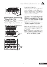
Страница 5: ...another SR or other amplifier 9 Stereo Parallel Bridge Switch In Stereo operation two separate signals are treated separately by channels 1 and 2 of the amplifiers In Parallel operation one signal is...

Страница 6: ...he amplifier is turned off before you change any output connections Loose screw terminals insert wire connectors under screws Tighten screw terminals Direct Low Impedance Output connection bridge mono...

Страница 7: ...er to the Rear Panel section on page 5 Low Impedance and Distributed Speakers If your application calls for connection of an 8 ohm speaker and a distributed line to the same amplifier channel the SR70...

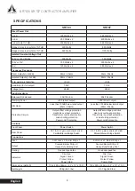
Страница 8: ...n 100dB below rated output 20Hz 20kHz Protection Circuits Output offset voitage protection Heat sink overheat protection Transformer overheat protection Load shorting protection Power on off protectio...

Страница 9: ...9 SR703 SR707 AMPLIFICADOR DE POTENCIA PARA CONTRATISTAS Espa ol...

Страница 10: ...s a la salida Para evitar descargas el ctricas aseg rese de que la cubierta este encima de los terminales de salida y no toque ning n cable de altavoz que este expuesto mientras el amplificador este o...

Страница 11: ...SR o a cualquier otro amplificador 9 Selector Est reo Paralelo Bridge En operaci n est reo dos se ales separadas ser n transmitidas por los canales 1 y 2 de los amplificadores En operaci n en Paralelo...

Страница 12: ...or este apagado antes de cambiar cualquier conexi n de salida Liberal los tornillos de los terminales inserte las conexiones de los cables debajo de los tornillos Apriete firmemente los tornillos de l...

Страница 13: ...er n ajustarse independientemente Por favor referirse a la descripci n previa del Panel Trasero Altavoces Distribuidos y de Baja Impedancia en los Amplificadores SR703 y SR707 Si sus aplicaciones nece...

Страница 14: ...Impedancia de Entrada Balanceada Desbalanceada 20k 10k ohm 20k 10k ohm Factor de Amortiguaci n Damping 200 entrada directa 200 entrada directa Relaci n S R Menor a 100dB debajo de la salida medida 20...

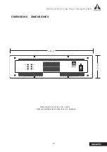
Страница 15: ...15 SR703 SR707 CONTRACTOR AMPLIFIER Appendix DIMENSIONS DIMENSIONES Measurements are shown in mm inches Todas las medidas est n mostradas en mm pulgadas 132 5 2 480 19...

Страница 16: ...www asystems sys com...

Отзывы: