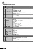
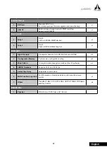
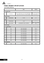
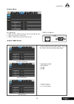
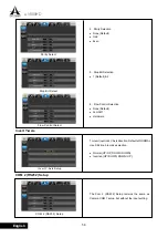
A SYSTEMS AV800HD Скачать руководство пользователя страница 56

54

AV800HD

English

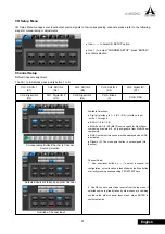
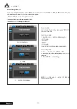
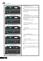
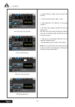
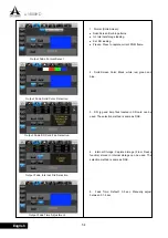
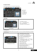
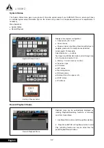
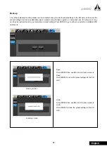
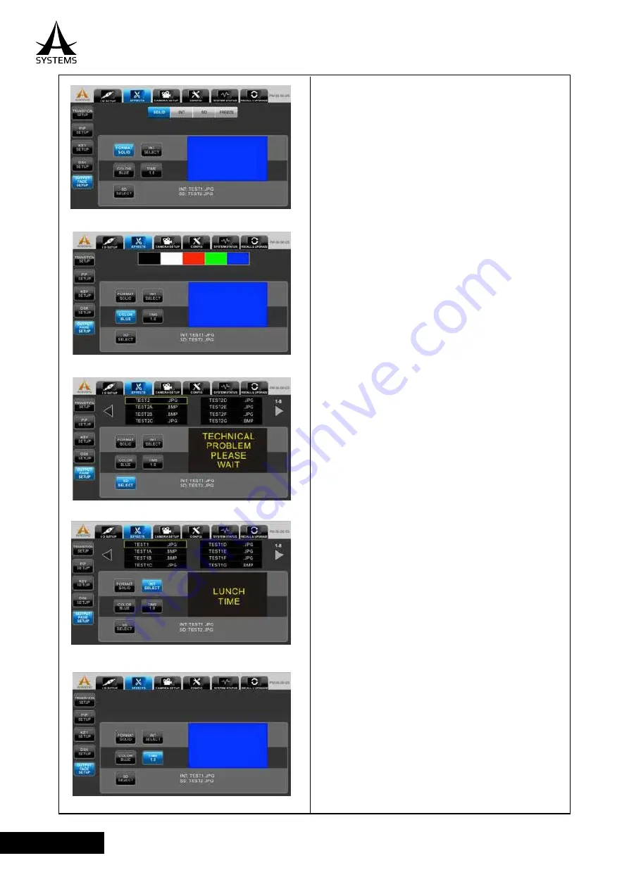
Output Fade Format Select

Output Fade Solid Color Selection

Output Fade SD Card File Selection

Output Fade Internal File Selection

Output Fade Time Adjustment

1.  Format (Solid Screen):

  Solid Screen: Built-in patterns.

  Int: Internal storage loading.

  Ext: SD loading.

  Freeze: Press to capture current PGM frame.

2.    Solid  Screen  Color:  Black,  white,  red,  green  and 
blue.

3.  SD: jpg and bmp files located in SD card can be 
used. The selection method is same as DSK.

4.    Internal  Storage:  Captured  image  (From  Freeze 
function) stored in internal storage can be used. The 
selection method is same as DSK.

5.    Fade  Time:  Default:  0.5  sec.  Manually  adjust 
between 0.1-5 sec.

Содержание AV800HD

Страница 1: ...User s Manual Multi Format Video Switcher AV800HD ...

Страница 2: ...en the apparatus has been damaged in any way such as power supply cord or plug is damaged liquid has been spilled or objects have fallen into the apparatus has been exposed to rain or moisture does not operate normally or has been dropped 15 CAUTION These servicing instructions are reduce the risk of electric shock do not perform any servicing other than that contained in the do so 16 building in ...

Страница 3: ...ug should be one that is within easy reach and readily accessible Placement This device may interfere with radio and television reception Do not use this device in the vicinity of such receivers Noise may be produced if wireless communications devices such as cell phones are operated in the vicinity of this unit Such noise could occur when receiving or initiating a call or while conversing Should ...

Страница 4: ...sliders or other controls and when using its jacks and connectors Rough handling can lead to malfunctions When disconnecting all cables grasp the connector itself never pull on the cable This way you will avoid causing shorts or damage to the cable s internal elements A small amount of heat will radiate from the unit during normal operation When you need to transport the unit package it in the box...

Страница 5: ...l Input output Ports 11 Front View 12 Connecting External Equipment 13 About Input Formats 13 Connecting Source Equipment 14 Making SDI Connections 14 Connecting a Computer or Interface Equipment 15 Making a Interface Connection 15 Connecting Output Equipment 16 Connecting a Projector 16 Connecting an External Recording Storage 16 Tally Output 16 Basic Operation 18 Power on Sequence 18 Multiview S...

Страница 6: ...een 36 Preset Memory 36 Camera Control 37 Playback Recording 37 Recording 38 Playback 39 Setup Menu Operations 40 Main Controls 40 Main Menu 40 Asystems Virtual Webcam Emulation Setup Guide 59 Asystems Direct Streaming Setup Guide 61 System Specification 66 Preset Memory Specification 68 Top Panel Specification 68 Setup Menu Specification 69 Glossary 74 Asystems reserves the right to alter any inf...

Страница 7: ...eo via CAT5 6 cable and a full configurable cross point button array The AV800HD s built in Multiview screen can output up to 8 images from different sources to a single high resolution display eliminating the need for multiple HD source and preview monitors For added creativity the switcher offers a wide selection of wipe patterns and features a high quality chroma key for green screen applicatio...

Страница 8: ...ids If a cleaning chemical is to be used carefully read through the precautions for its use Precaution to be observed during production This product s image switching and image effect functions can be used to produce images which flicker rapidly or images which change rapidly However bear in mind when using these functions in production that the kinds of images produced may have an adverse effect ...

Страница 9: ...oduct please carefully inspect the included items in the unlikely event of any missing or damaged items please contact your authorized retailer distributor for replacements AV800HD AV800HD Owner s Manual Power Cable User s Manual Multi Format Video Switcher AV800HD ...

Страница 10: ... an infinitesimal electrical charge which is absolutely harmless However if you are concerned about this connect the ground terminal with an external ground When the unit is grounded a slight hum may occur depending on the particulars of your installation If you are unsure of the connection method contact the nearest Asystems Service Center or an authorized Asystems distributor for detailed inform...

Страница 11: ...Knob Scroll through menu options 2 Record and Playback Controls EXT DRV External Drive LED Lit when external USB storage device is connected record and playback functions will not function if this LED is off Record Button Set player into record standby mode Play Pause Button Toggle between play pause and record Playback Mode Toggle between play and pause Record Mode Toggle between record and recor...

Страница 12: ...stream Key DSK Button Toggle DSK on and off 10 Output Fade Output Fade Button Toggle Output Fade on and off 11 Output Indicators LED 1 PGM Out is active LED 2 AUX Out is active LED 3 PIP Mode is on LED 4 KEY Mode is on LED 5 DSK is on 12 Input Indicators LED 1 to B Indicate if input is active 13 Wipe Pattern Section Button 1 to 12 Select the wipe pattern enable Wipe Pattern Transition Mode 14 Joys...

Страница 13: ...SK Setup Menu on and off enable DSK level control Level Knob Adjust DSK transparency level Rear Panel Input output Ports 1 Tally 1 2 Tally 1 CH 1 5 Tally 2 CH 6 10 2 COM 1 RJ 45 for MK20HD camera PTZ controls Require USB to RS422 adapter 3 COM 2 DB 9 RS232 communication port for remote control application 4 Multiview Multiview monitor output Interface 1 10 2 4 13 3 7 8 9 12 14 16 15 5 6 11 PIN Dat...

Страница 14: ...CAT 5 6 Interface one Interface and one 3G SDI can be configured as PVW PGM or CH 1 to B 12 AUX 2 OUT One Interface can be configured as PVW PGM or CH 1 to B Note The internal audio signal is set to AUX 1 unless PGM is set to AUX 2 only else the audio signal remains in AUX 1 If AUX 1 and AUX 2 both set to PGM AUX 1 takes priority and the audio signal remains in AUX 1 13 SDI Input 1 to 4 Supports 4...

Страница 15: ...t Formats Signals of the formats shown below can be input from source equipment SDI 480i 59 94 576i 50 720p 50 720p 59 94 1080i 25 1080i 29 97 1080p24 1080p 29 97 1080 50p 1080 59 94p Interface PC 640x480 60 Hz 800x600 60 Hz 1024x768 60 Hz and 1920x1080 60Hz CE 480i 59 94 576i 50 720p 59 94 720p 50 1080i 59 94 1080i 50 1080p 24 1080p 29 97 1080p 59 94 and 1080p 50 Interface Interface Interface Int...

Страница 16: ...4 3G SDI Connect SDI equipment such as video cameras or video decks to the SDI IN connectors SDI inputs are default to cross point channels 1 through 4 Can be reconfigured to other cross point channels 3G SDI 3G SDI 3G SDI 3G SDI Interface Interface 2 Interface 3 Interface 4 Interface Interface ...

Страница 17: ...figured to other cross point channels For equipment capable of Interface output make the connection using a conversion cable RJ45 1080P60 MK20HD PC Interface 1080P60 Interface 1080P60 Interface 1080P60 Interface 2 Interface 3 Interface 4 InterfaceO Interface 2 Interface 3 Interface 4 QPPPPO Interface Interface Interface 2 Interface 3 Interface 4 Interface Interface 2 Interface 3 Interface 4 Interf...

Страница 18: ...top panel will light up indicating the device is ready to use Tally Output The tally connector comes with tally output output enable power supply or fan alarm output pins The output signals from the tally output pins are for lighting the tally lamps and these outputs are open collector outputs D sub 15 pin male Camera 3 Tally Camera 2 Tally Camera 1 Tally Tally Splitter Camera 4 Tally Camera 5 Tal...

Страница 19: ...5 PVW 10 PGM 5 Open collector output Tally output of CH 5 PGM 11 15 NC No Connection Pin No Signal Name Input output Description 1 PVW 6 Open collector output Tally output of CH 6 PVW 2 PGM 6 Open collector output Tally output of CH 6 PGM 3 PVW 7 Open collector output Tally output of CH 7 PVW 4 PGM 7 Open collector output Tally output of CH 7 PGM 5 PVW 8 Open collector output Tally output of CH 8 ...

Страница 20: ...as well as a guideline for how to properly execute these commands Power on Sequence Starting Up Connect a 1080p TV or computer monitor via Interface to Multiview output Use a Interface adapter for Interface connection Multiview output is fixed to 1080p 59 94 Please disable TV s over scan option for full screen viewing AV800HD Copyright by ASYSTEMS All rights reserved ...

Страница 21: ...t with no special effect PGM content is directly from channel source PIP Mode PGM output with PIP PGM contents consist of two channel sources Main and PIP in PIP format KEY Mode PGM output with KEY effects PGM contents consist of two channel sources Foreground and Background in Key binding format 3 CH 1 to B Section Source Monitors Monitor the video from source equipment connected to channel 1 to ...

Страница 22: ...n each channel screen without an active input source PGM Label Location Upper left corner of PGM screen PGM Label Location Upper left corner of PVW screen Channel 1 to 6 Label Location Upper left corner of Channel screen Channel 7 to B Label Location Upper left corner of Channel screen Channel 7 A Text Default Channel 7 toggle between Channel 7 A Channel 8 B Text Default Channel 8 toggle between C...

Страница 23: ... channel to PVW 2 Selected PST button will light up in green corresponded Multiview screen will have a green border around selected channel content will be displayed in PVW screen Note 1 DSK is permanently assigned to Channel B Note 2 If transition is performed prior a source is assigned to PGM PVW will be transferred to PGM and PVW will become blank screen Asystems logo screen Channel 5 selected ...

Страница 24: ...view screen will have a red border around selected channel content will be displayed in PGM screen Note 1 DSK is permanently assigned to Channel B Note 2 If transition is performed prior a source is assigned to PVW PGM will be transferred to PVW and PGM will become blank screen Asystems logo screen Channel 2 selected Red Boarder indicates Channel 2 is being displayed in PGM Channel 5 in PVW Channe...

Страница 25: ...n or switch back transition mode 1 Transition Time Adjustment When in Time Adjustment Mode the LED is displayed in second format with a decimal point after the 1st MSB Use TIME FRAME knob to adjust Range 0 00 to 9 99 seconds 2 Transition Frames Adjustment When in Frame Transition Mode the LED is displayed in frame format with no decimal points Use TIME FRAME knob to adjust Range 000 to 999 frames ...

Страница 26: ...instant transition PIP Operation Mode Operating Mode 2 Enable PIP preview will switch the top panel controls to PIP operating mode Press PIP 1 4 to determine starting location these buttons also serve as 4 PIP preset memory locations Scale Size Joystick will switch to PIP Mode PIP KEY LED lit press SEL button to toggle joystick controls between PIP and Camera Multiview screen will switch to PIP mo...

Страница 27: ...2 CH6 CH3 CH7 A CH4 CH8 B Assign main PIP source Assign PIP source Use PGM cross point buttons to assign main PIP source Channel B cannot be used Use PST cross point buttons to assign PIP sub source Channel assigned to DSK cannot be used 1 PIP starting location always follow button s default position Upper right upper left lower right and lower left use the joystick to position the PIP location an...

Страница 28: ...exit the PIP transition to KEY transition PIP Transition Controls PIP Transition Complete PGM PIP Preview PVW Screen PGM PVW CH1 CH1 CH2 CH3 CH7 A CH8 A CH4 CH5 CH6 CH5 CH2 CH6 CH3 CH7 A CH4 CH8 B PIP Transition Types PIP transition follows the same rule as Wipe Pattern transition 1 AUTO PIP fades into PGM according to defined transition time 2 Manual PIP fades into PGM according the T Bar movemen...

Страница 29: ...l switch to KEY Mode Scale Size PIP KEY LED is lit Controls in KEY mode Press SEL to toggle joystick controls between KEY and Camera Enable KEY Mode KEY MultiView Screen Joystick in KEY Mode PGM Foreground Background Background PGM PVW CH1 CH1 CH2 CH3 CH7 A CH8 A CH4 CH5 CH6 CH2 CH6 CH3 CH7 A CH4 CH8 B Foreground CH5 ...

Страница 30: ...eground Source Channel B cannot be used 4 Foreground will be displayed in PVW screen with eyedropper KEY effect will only apply to PGM when transition is completed Assign foreground Assign background PGM Background PGM PVW CH1 CH1 CH2 CH3 CH7 A CH8 A CH4 CH5 CH6 CH2 CH6 CH3 CH7 A CH4 CH8 B CH5 PVW PGM PVW Background PGM PVW CH1 CH1 CH2 CH3 CH7 A CH8 A CH4 CH5 CH6 CH2 CH6 CH3 CH7 A CH4 CH8 B Foregr...

Страница 31: ... LED is not lit to PIP KEY 3 Use the Position Joystick to move the eyedropper around the KEY Preview screen the content of eyedropper shows the current custom color and color value is listed current filter color default is pure Green on lower left corner RGB of KEY Preview 4 Press ENTER button to select custom key color from the KEY Preview Screen New color value is shown at lower left corner and ...

Страница 32: ...ound instantly appears in PGM 4 Level Adjust Foreground transparency level KEY Level Knob End Transition 100 100 75 75 50 50 25 25 0 0 End Transition Starting Point Starting Point Background PGM PVW CH1 CH1 CH2 CH3 CH7 A CH8 A CH4 CH5 CH6 CH2 CH6 CH3 CH7 A CH4 CH8 B Foreground CH5 R 000 G 252 B 010 GREEN AUTO KEY Transtion Manual KEY Transition CUT KEY Transition KEY Level Adjust KEY Level Adjust ...

Страница 33: ... C C CH H H1 H1 H H1 1 H1 C C C CH H H H1 1 1 CH H H1 CH2 C CH2 H H H2 2 2 C C C CH2 H H2 2 H2 CH2 2 H H H H2 2 2 2 CH CH H H2 H2 H2 2 H2 2 2 C 2 2 CH H2 2 CH2 2 2 C CH2 CH5 H5 H5 C 5 H5 5 H CH CH5 CH CH CH H5 C 5 C CH5 CH5 C C CH H CH CH5 CH5 C C C CH H5 CH5 CH CH5 CH5 CH5 5 5 C CH5 CH5 H CH6 CH6 C 6 CH CH CH CH C CH C CH C C CH C C 2 2 2 2 2 2 2 2 2 2 2 2 2 2 2 2 2 2 2 2 2 2 2 2 2 2 2 2 2 2 2 2 ...

Страница 34: ...gh quality and professional Apply DSK 1 DSK is fixed to Channel B internal storage location with lower right corner DSK label displayed refer to Setup Menu DSK Setup section for in depth DSK setup 2 Press DSK button to apply DSK on PGM output DSK button is lit in amber when it is active press DSK button again to remove DSK from PGM LED will be dimmed CH1 CH3 CH7 A CH8 B DSK CH4 CH6 PVW CH5 PGM CH2...

Страница 35: ...EL to open DSK Setup Menu the button will light up in amber 2 Adjust DSK transparency level with DSK Level Knob Please refer to Setup Menu DSK Setup for more in depth DSK settings 3 Press DSK SEL or MENU to close Setup Menu LED will be dimmed 1 Press OUTPUT FADE button to apply output fade to PGM button will flash in amber 2 Output fade will overcast all PGM contents including the DSK channel The ...

Страница 36: ...the SIZE knob to adjust image size Clockwise Increase size Maximum up original image Counter Clockwise Decrease size Minimum up to 10 of original image size 4 Use the POSITION joystick to position the viewing center location Over scaled Viewable area window can be moved around the total image area 5 Press ENTER to complete and exit the adjustment Image of CH5 will now convert to modified effect wi...

Страница 37: ...bled 2 Use the SIZE to adjust image size Clockwise Increase size Maximum up to 10X of original image Counter Clockwise Decrease size Minimum up to original image size 3 Use the POSITION joystick to position the viewing center location Over scaled Viewable area window can be moved around the total image area 4 Press ENTER to complete and exit the adjustment image of PGM output will now convert to m...

Страница 38: ...ocation Preset memory settings are divided into 4 groups Referred to as Pages of 8 The LED Page Indicator signals what page is being accessed Press the PAGE button to select between pages 1 to 4 memory allocation of each page are as follow Page 1 Preset memory 1 to 8 Page 2 Preset memory 9 to 16 Page 3 Preset memory 17 to 24 Page 4 Preset memory 25 to 32 Recall Preset Memory Select and press the d...

Страница 39: ...to 1080p30 Supports H 264 MP4 and AVI recording formats 2 EXT DRV LED New Drive Detection LED will flash during device detection nd configuration LED will become solid once the device is properly recognized LED ON Either an external storage device or PC In H 264 RJ45 Webcam Emulation Mode refer to Setup Menu Recording section is connected the Playback Recording buttons are functional only when the...

Страница 40: ...each recording The default recording format will follow the pattern below File format AVmmddyynnnn AV Header code mm Month of today 01 to 12 dd Day of today 01 to 31 yy The last 2 digits of this year nnnn Sequence number 0001 to 9999 The sequence number always starts from 0001 at each day 5 Press MENU Button during recording operation will bring up the Recording Menu Refer to Setup Menu Recording ...

Страница 41: ...back Menu press MENU ENTER button to confirm playback selection PLAY indicator will stop flashing and time counter counting Playback preview icon will also change to PLAY press PLAY PAUSE button again will pause the playback 3 Press Playback Stop Button to stop playback preview playback timer will reset to zero 4 End Playback Press MENU button to close Playback Menu and end playback operation CH A...

Страница 42: ...o open Main Menu 2 Press MENU again or ESC to close Main Menu 3 Use buttons to navigate through Main Menu selection 4 Press buttons to navigate through sub menu selection PVW PGM CH3 CH7 A CH4 CH3 CH8 B Menu Controls Setup Menu Location Button Definitions Press the MENU Button to bring up the menu press it again to close the menu Press the MENU Button in a sub menu or adjustment menu will close th...

Страница 43: ...ding Button Channel to Channel Source Selection Override a Channel Input Available Selections Digital Interface In 1 4 D1 D4 Interface Input ource 1 through 4 SDI IN 1 4 S1 S4 Multi Zoom 1 8 M1 M8 Reserve space for Multi Zoom composing maximum 8 only assignable from Multi Zoom composing DSK Contents of this channel will be displayed when DSK is activated Disable X The cross point button is not ass...

Страница 44: ...T LED is selected The PVW screen and selected source channel borders are Blue indicating Multi Zoom adjustment is in progress 3 The selected source channel image will be placed into the Preview screen 4 Once image is placed in the Preview screen a small green rectangular will appear in the center of Preview screen use joystick to place the zoom area 5 Use SIZE knob to adjust zoom size from 10 100 ...

Страница 45: ...43 AV800HD English Multi Zoom Area Selected Select a New Zoom Area Cross Point Channel assigned to Multi Zoom PVW PGM PVW CH1 CH1 CH2 CH3 CH7 A CH8 A CH4 CH5 CH6 CH2 CH6 CH7 A CH4 CH8 B CH5 PVW ...

Страница 46: ...nal digital USB audio AV IN Setup Menu D1 Setup D1 set to P60 D2 disabled Cursor Location Use to select Audio Output Setup press ENTER to sub menu selections Audio Source Select 1 Use SEL knob to scroll through top menu bar EXT Analog EXT USB Default X No audio Press ENTER to confirm audio source selection Audio Delay Setting 1 Use to place cursor to Delay button 2 Use SEL knob to set audio delay ...

Страница 47: ...selection Use to select sub menu options The default system settings are AUX 1 Resolution 1080 AUX 1 Source PGM AUX 2 Resolution 1080 AUX 2 Source PVW Frame Rate PGM 60P Video System NTSC PGM Output Resolution Selection AUX Analog Output Resolution Selection AUX 1 and AUX 2 Output Resolution Selection PAL 1080 720 480 576 AUX 1 and AUX 2 Source Selection PVW PGM CH 1 CH B ...

Страница 48: ...46 AV800HD English NTSC Frame Rate Select PAL Frame Rate Select Frame Rate Selection Selection only applies to PGM PAL 60P 50P 30P 25P 30i 25i Video System NTSC PAL ...

Страница 49: ...n the Effect Setup Menu you can edit the following settings Menu Selection Transition Setup PIP Setup Key Setup DSK Setup Output Fade Setup Transition Setup The 12 wipe pattern buttons which are used as the basis for wiping and transitioning into another input source image you can manually adjust how long the wipe patterns will take effect in time or frames program and assign wipe patterns ...

Страница 50: ...s 0 30 frames max frame interval will be limited by output frame rate 30 frames 30 and 60 Hz NTSC 25 frames 25 and 50 Hz PAL Use SEL knob to adjust clockwise CW frame counter clockwise CCW time 4 Define Wipe Pattern Buttons Use button to move cursor to Wipe Pattern Button icon use buttons to select a Wipe Pattern Buttons At each Wipe Pattern button use SEL knob to scroll through pattern list push ...

Страница 51: ...can be called up by Setup Menu selection or directly by top panel Key SEL button PIP Setup Menu Width Adjustment PIP Border Color Select 1 Selection Width PIP border width 0 20 lines Default 0 no border Color PIP border color White black red blue or green Default white 2 Width Use SEL knob to adjust PIP border width ...

Страница 52: ...m Default Green Custom color can only be changed when Key SEL button is enabled by using the eyedropper function Press ENTER to confirm selection 3 Key Filter Range Adjustment Use SEL knob to adjust range push ENTER to confirm selection 4 Edge Adjustment Use SEL knob to adjust push ENTER to confirm selection 5 Key Border Width Adjustment Use SEL knob to adjust push ENTER to confirm selection 6 Key...

Страница 53: ...le image files will be shown in bottom menu and image can be previewed in the lower left window Use the select knob to scroll through the file list and use ENTER to confirm selection DSK Setup DSK channel is fixed to Cross Point Channel B In Ext Key mode it is the Key Fill and can not be assigned to othe Cross Point Channels DSK menu will also pop up when DSK SEL button is enabled Press ENTER to g...

Страница 54: ...t 0 joining edge sharpness 6 EXT KEY When enabled the EXT KEY button will become solid EXT KEY will share the same settings with SOURCE and same input selection DSK and EXT KEY cannot be the same source 7 DSK Level Use the top panel DSK level knob to adjust the transparency level DSK transparency level 10 100 100 solid NOTE When using EXT KEY the background file must be stored in the INT Internal ...

Страница 55: ...d EXT KEY Source Selection Output Fade Setup In Output Fade Setup menu you can edit and adjust the type of fade out screen of the output Lower left corner displays the current output fade image use SEL to make selection and adjustment ...

Страница 56: ...tterns Int Internal storage loading Ext SD loading Freeze Press to capture current PGM frame 2 Solid Screen Color Black white red green and blue 3 SD jpg and bmp files located in SD card can be used The selection method is same as DSK 4 Internal Storage Captured image From Freeze function stored in internal storage can be used The selection method is same as DSK 5 Fade Time Default 0 5 sec Manuall...

Страница 57: ...control communication port Invert Y Axis Camera tilt control COM 2 RS232 remote control protocol port Camera COM 1 Setup 1 Please wait 30 seconds for the system to recognize the converter before any setting change begins 2 Baud Rate Selection 9600 Default 115200 384000 3 Data Bit Selection 5 6 7 8 Default COM Port Configuratio ...

Страница 58: ...n 5 Stop Bit Selection 1 Default 2 6 Flow Control Selection None Default Xon Xoff Hardware To invert joystick s Y Axis direction Default at NORMAL Use SEL knob to make selection Normal UP UP DOWN DOWN Inverted UP DOWN DOWN UP The Com 2 RS232 Setup remains the same as Camera COM 1 setup but without the input setting Invert Y Axis COM 2 RS232 Setup ...

Страница 59: ...e storage and video streaming 1 Internal Storage 5 GB reserve space INT is the root directory for internal storage Press ENTER to enter file management use to go to Next or Previous page When available Use to browse through file selection Press ENTER to Text Open file functions bottom menu options open File Management Functions Use select function press ENTER to execute function Delete Delete a fi...

Страница 60: ... turn HDCP On and Off When HDCP is not turned on HDCP encrypted video sources will not be allowed to pass through PGM NOTE1 During streaming and recording PGM content is HDCP encrypted and SDI output is disabled NOTE2 When HDCP is already enabled and user attempts to connect other HDCP devices into an interface ports that was previously unoccupied please turn the HDCP function off and then on agai...

Страница 61: ...gs while leaving the Public network settings turned on Turn off your antivirus software for installation to prevent installation being blocked Alternatively you can add the iNETCAM exe as a trusted source and NETCAM X 86 AX and NETCAM X 64 AX to the exception list 3 Set up virtual webcam s IP address by automatic detection method DHCP 4 Auto IP address Connect both video switcher s streaming outpu...

Страница 62: ...will automatically pop up asking whether you would like to the NETCAM IP address Click Yes and you will be prompted to enter the IP address that is assigned to your AV800HD in the System Status menu Enter the IP address into the box and you are all set to go A NETCAM desktop icon will be set after the installation should you need to reset the IP address just simply click on the desktop icon and re...

Страница 63: ...ing on the type of streaming platform you use some of the setup options and selections may vary slightly but the overall rules of this setup guide do apply Asystems Direct Streaming Setup Guide The AV800HD supports direct stream on video streaming platforms and it follows standard Real Time Streaming Protocol RTSP which is a network control protocol designed for use in entertainment and communicat...

Страница 64: ...layback menu can be automatically displayed by invoking Playback Recording functions or manually open from Setup Menu 1 Use Menu SEL knob to scroll through file selection 2 Press Menu ENTER or Play Pause button to start Play recording function can only be acted from top panel Playback Record buttons System Status Screen Editing Channel Label Record Playback Menu System Status The System Status men...

Страница 65: ...ll Selection All Reset all data to original factory default Preset Reset preset memory only Key Reset current Key Setup Menu only DSK Reset current DSK Setup Menu only Channel Setup Reset current Channel Setup Menu only Audio Output Setup Reset current Audio Setup Menu back to default values Video Output Setup Reset current Video Output Setup Menu back to default values Menu only PIP Reset current...

Страница 66: ...r data will be saved while performing FW upgrade OFF All data will be erased while performing FW upgrade Firmware Upgrade Place FW data in the SD card If FW data exists in the SD card it will be displayed Use SEL knob to select the FW from the list Press ENTER to confirm selected FW data Continue prompt screen will pop up Use to select between Yes and No Press ENTER again to proceed When upgrade c...

Страница 67: ... Press ENTER to load the preset settings in the SD card Backup The Preset Backup function allows user to manually backup the all 32 preset settings to the SD card in the event the preset settings have been accidentally wiped erased during firmware upgrade or overwritten due to human error they can then be restored back to your accustomed preset settings Press ENTER to go to sub menu selection Avai...

Страница 68: ...up to 1080p60 RJ 45 CAT 5 Interface x1 x1 x1 2 AUX 2 Out Interface Supports Interface up to 1080p60 x1 3 Multiview Interface Fixed to 1080p60 x1 4 Video Streaming RJ 45 LAN virtual webcam PGM output Supports up to 1080p30 Note DHCP function requires external DHCP server x1 AUDIO I O 1 USB 2 0 Input Type A Digital audio in x1 2 Stereo Phone Jack Input 6 3mm Analog audio in x1 3 Stereo Phone Jack Ou...

Страница 69: ...nput Channels Crosspoint channels for AV IN Multi Zoom and DSK x10 2 Configuration Memory Custom setup configuration setting x32 3 Wipe Pattern 12 programmable wipe pattern buttons from 23 patterns x12 4 SMPTE Timebase Supports 29 97 and 59 94 fps 5 Audio Time Delay Adjustable to match video 6 Multi Functions Joystick For PiP location I O scale and size control remote camera control x1 7 Others Tr...

Страница 70: ...attern 1 Position Button 1 to 12 12 III PIP 1 Position Button 1 to 4 1 2 Size Position Last adjusted PIP size and position Button 1 size and posi tion III Input Scale A Input Channel 1 CH1 None Scaled Data None 2 CH2 None Scaled Data None 3 CH3 None Scaled Data None 4 CH4 None Scaled Data None 5 CH5 None Scaled Data None 6 CH6 None Scaled Data None 7 CH7 None Scaled Data None 8 CH8 None Scaled Dat...

Страница 71: ...K D2 7 CH7 S1 4 D1 4 X and DSK D3 8 CH8 S1 4 D1 4 X and DSK D4 9 CHA S1 4 D1 4 X and DSK X 10 CHB S1 4 D1 4 X and DSK DSK B AV IN Setup 1 D1 Frame Rate P30 and P60 P30 Audio Source Default USB and Analog Default Audio Delay 0 00 to 9 99 seconds 0 00 2 D2 Frame Rate P30 and P60 P30 Audio Source Default USB and Analog Default Audio Delay 0 00 to 9 99 seconds 0 00 3 D3 Frame Rate P30 and P60 P30 Audi...

Страница 72: ...econds 0 00 3 S3 Frame Rate P30 and P60 P30 Audio Source Default USB and Analog Default Audio Delay 0 00 to 9 99 seconds 0 00 4 S4 Frame Rate P30 and P60 P30 Audio Source Default USB and Analog Default Audio Delay 0 00 to 9 99 seconds 0 00 5 D2 Frame Rate P30 and P60 P30 Audio Source Default USB and Analog Default Audio Delay 0 00 to 9 99 seconds 0 00 C OUTPUT Setup 1 PGM Resolution PAL 1080 720 4...

Страница 73: ...n Button 6 1 to 24 6 8 Wipe Pattern Button 7 1 to 24 7 9 Wipe Pattern Button 8 1 to 24 8 10 Wipe Pattern Button 9 1 to 24 9 11 Wipe Pattern Button 10 1 to 24 10 12 Wipe Pattern Button 11 1 to 24 11 13 Wipe Pattern Button 12 1 to 24 12 B PIP Setup 1 Width 0 to 20 0 2 Color White Black Red Blue and Green Red C Key Setup 1 Filter Green Blue Black White and Custom Green 2 Filter Range 0 to127 25 3 Edg...

Страница 74: ...t Key Int 2 Int fil Selected file WELCOME image fil 3 SD fil Selected file Blank 4 Filter Black and White Black 5 Edge 0 to 100 0 6 Ext Key Int SD and X Off Off III Config Menu Recording Setup 1 Format AVI Webcam and H 264 H 264 2 Audio Output Level 0 to 100 50 ...

Страница 75: ...l and Inverted Normal C COM 2 Setup 1 Baud Rate 9600 115200 and 384000 9600 2 Data 5 6 7 and 8 8 3 Parity None Odd and Even None 4 Stop 1 and 2 1 5 Flow Control None Xon Xoff and Hardware None V System Status A Input Labeling 1 CH1 Input Text Blank 2 CH2 Input Text Blank 3 CH3 Input Text Blank 4 CH4 Input Text Blank 5 CH5 Input Text Blank 6 CH6 Input Text Blank 7 CH7 Input Text Blank 8 CH8 Input T...

Страница 76: ...ital video interface standard DVI I can handle both digital signals and analog signals Frame Synchronizer A function which matches the synchronization of non synchronized video input signals Freeze A function which continues the display of the same image creating the impression that the image has been frozen FTB Fade to Black This is the effect where the background image is faded out to the black ...

Страница 77: ...erface The standard by which video signals in various SD and HD formats are transmitted along a single coaxial cable SMPTE Time base A set of cooperating standards to label individual frames of video or film with a time code defined by the Society of Motion Picture and Television Engineers in the SMPTE 12M specification Tally The signal which outputs the program output statuses of the input signal...

Страница 78: ......

Страница 79: ......

Страница 80: ...www asystems sys com ...

Отзывы: