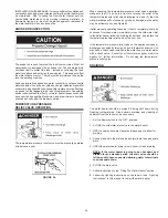
background image

15

SEDIMENT TRAPS

A sediment trap shall be installed as close to the inlet of the water
heater as practical at the time of water heater installation. The
sediment trap shall be either a tee fitting with a capped nipple in the
bottom outlet or other device recognized as an effective sediment
trap. If a tee fitting  is used, it shall be installed in conformance with
one of the methods of installation shown in Figures 12 and 13.

Contaminants in the gas lines may cause improper operation of the
gas control valve that may result in fire or explosion. Before attaching
the gas line be sure that all gas pipe is clean on the inside. To trap
any dirt or foreign material in the gas supply line, a drip leg
(sometimes called a sediment trap) must be incorporated in the
piping.  The drip leg must be readily accessible. Install in accordance
with the “Gas Piping” section. Refer to the current edition of the
National Fuel Gas Code (ANSI Z223.1/NFPA 54) or the Natural
Gas and Propane Installation Code (CAN/CSA B149.1).

FIGURE 14.

FILLING THE WATER HEATER

Never use this water heater unless it is completely full of water. To prevent
damage to the tank, the tank must be filled with water. Water must flow
from the hot water faucet before turning “ON” gas to the water heater.

To fill the water heater with water:
1. Close the water heater drain valve by turning the handle to the right

(clockwise). The drain valve is on the lower front of the water heater.

2. Open the cold water supply valve to the water heater.

NOTE: The cold water supply valve must be left open when
the water heater is in use.

3. To insure complete filling of the tank, allow air to exit by opening the

nearest hot water faucet.  Allow water to run until a constant flow is
obtained.  This will let air out of the water heater and the piping.

4. Check all water piping and connections for leaks.  Repair as needed.

VENT PIPE ASSEMBLY

There are three parts of the vent pipe assembly that connect the water
heater exhaust (located on the lower back side of the water heater) to
the inlet of the blower assembly (mounted on top of the water heater) as
shown in Figure 1. These parts will need to be assembled according to
the instructions in the VENT PIPE PREPARATION section of this manual.
These PVC parts should be assembled with ASTM D-2564 grade cement.

Assemble Vent Pipe Assemblies #1, #2 and #3 (See Figure 1) prior
to cementing. The preferred orientation of Vent Pipe Assembly #1
(Condensate U-Assembly) is shown in Figure 16. However this
assembly may be rotated to a different orientation as needed for the
specific installation requirements. Note the rotational orientation of
each part by marking a line several inches long across the joints.The
long tube of Vent Pipe Assembly #2 should be approximately vertical.
If it is found that either of the two pieces of pipe in Vent Pipe Assembly
#2 are too long for proper fit-up, then remove as little material as
possible to improve the fit-up. Keep in mind that the pipes will insert
slightly further into the elbows when cement is applied as it acts as
a lubricating agent. The vertical distance from the bottom of the
Condensate U-Assembly to the floor that supports the water heater
should be approximately 0.25" (0.64 cm), see Figure 16. Disassemble
the parts and cement back together using the alignment marks. After
the cement dries, attach the assembly to the blower and the water
heater exhaust using the supplied rubber boots and hose clamps.

A condensate trap is incorporated in the bottom of this vent pipe assembly.
See the CONDENSATE section of this manual for further details.

VENTING

Содержание RESIDENTIAL GAS WATER HEATER

Страница 1: ...URFACE IGNITION NOT FOR USE IN MANUFACTURED MOBILE HOMES ALL TECHNICAL AND WARRANTY QUESTIONS SHOULD BE DIRECTED TO THE LOCAL DEALER FROM WHOM THE WATER HEATER WAS PURCHASED IF YOU ARE UNSUCCESSFUL PL...

Страница 2: ...onal Fuel Gas Code as it relates to the installation of gas fired water heaters The qualified installer must also be familiar with the design features of water heaters and have a thorough understandin...

Страница 3: ...3 GENERAL SAFETY...

Страница 4: ...4 GENERAL SAFETY...

Страница 5: ...r whose name appears on the rating plate 5 Carefully plan the place where you are going to put the water heater Correct combustion vent action and vent pipe installation are very important in preventi...

Страница 6: ...Shown D D Plastic Top E E On Off Switch F F Exhaust Tee G G Elbow GET TO KNOW YOUR WATER HEATER GAS MODELS A Vent Pipe B Anode C Hot Water Outlet D Outlet 120 VAC F Gas Supply G Main Manual Gas Shut O...

Страница 7: ...so must be primed by filling half of the loop with water prior to operating the water heater Carefully plan the location of the loops and straight sections of hose prior to cutting hoses If necessary...

Страница 8: ...than others These include the elderly children the infirm or physically mentally handicapped If anyone using hot water in your home fits into one of these groups or if there is a local code or state l...

Страница 9: ...installed Water heaters are sometimes installed in locations where leakage may result in property damage even with the use of a drain pan piped to a drain However unanticipated damage can be reduced o...

Страница 10: ...or exceeds the Energy Policy Act standards with respect to insulation and standby loss requirements making an insulation blanket unnecessary Should you choose to apply an insulation blanket to this he...

Страница 11: ...unicate directly or by ducts with the outdoors or spaces crawl or attic that freely communicate with the outdoors 1 When directly communicating with the outdoors each opening shall have a minimum free...

Страница 12: ...chemicals calcium and sodium chloride water softener salt waxes and process chemicals are typical compounds which are potentially corrosive Do not store products of this sort near the heater Also air...

Страница 13: ...installed directly into the fitting of the water heater designed for the relief valve Position the valve downward and provide tubing so that any discharge will exit only within 6 inches 15 2 cm above...

Страница 14: ...he water heater Use a soapy water solution not a match or open flame Rinse off soapy solution and wipe dry When installed at elevations above 2 000 feet 610 meters for standard models or 4 500 feet 1...

Страница 15: ...llow water to run until a constant flow is obtained This will let air out of the water heater and the piping 4 Check all water piping and connections for leaks Repair as needed VENT PIPE ASSEMBLY Ther...

Страница 16: ...e CAN CSA B149 1 Instructions on proper installation through a sidewall are provided in Figure 15 Plan the vent system layout so that proper clearances are maintained from plumbing and wiring Vent pip...

Страница 17: ...t and ABS Materials should use ASTM D 2235 Grade Cement If the water heater is being installed as a replacement for an existing power vented heater in pre existing venting a thorough inspection of the...

Страница 18: ...r housing 6 Make sure the ON OFF switch is in the OFF position and that the outer harness is connected from the blower control box to the connector on the bottom side of the gas valve 7 If the outer h...

Страница 19: ...ely one quarter inch 0 64 cm outside of the line This will allow the vent to easily slide through the opening The resulting gap will be covered up by the Vent Terminal cover plate Repeat this step on...

Страница 20: ...lashing or BOOT should be used to seal the pipe where it exits the roof The total vent system should not exceed the equivalent feet of pipe as listed in Table 1 Provide support for all pipe protruding...

Страница 21: ...o prevent any combustion gases escaping into the room If the plug is not securely tightened remove and reinstall using Teflon tape on the threads Once installed along with the rest of the vent configu...

Страница 22: ...r leaks will allow flue gas by products to disseminate into the room creating an unsafe environment and could cause illness asphyxiation and or even death FIGURE 24 Typical Installation for Vertical V...

Страница 23: ...nd above PRIMER It is recommended that Tetrahydrofuran THF be used to prepare the surfaces of pipe and fittings for solvent welding Do not use water rags gasoline or any other substitutes for cleaning...

Страница 24: ...make a second mark as the primer and cement will most likely destroy your first one Apply primer to the surface of the pipe and fitting socket with a natural bristlebrush Thisprocesssoftensandprepares...

Страница 25: ...nd HOTTER buttons together and holding for 1 second Then press the COOLER button until the WARM indicator light appears 2 Set the ON OFF switch on the blower control box to the OFF position 3 Turn off...

Страница 26: ...er s instructions for installation of the valves Before changing the factory setting on the thermostat read the Temperature Regulation section in this manual see Figure 26 Never allow small children t...

Страница 27: ...rod and the water The most common complaint associated with the anode rod is one of a rotten egg smell in the hot water The smell is a result of four factors which must all be present for the odor to...

Страница 28: ...Contact a qualified installer or service agency to replace a flooded water heater Do not attempt to repair the unit It must be replaced At least once a year a visual inspection should be made of the...

Страница 29: ...the temperature pressure relief valve discharge line and 2 that the water discharge will not cause any property damage as the water may be extremely hot see Figure 28 If after manually operating the...

Страница 30: ...ose connections or the relief valve DO NOT replace the water heater until a full inspection of all possible water sources is made and necessary corrective steps taken Leakage from other appliances wat...

Страница 31: ...en 4 36 Wall Plate 4 37 Flexible Tubing 38 Reducing Hose Barb Tee 39 Hose Barb Tee REPAIR PARTS LIST Not Shown Optional Now that you have purchased this water heater should a need ever exist for repai...

Страница 32: ...is energized wiring If the control does not energize the blower replace the Intelli Vent control If the blower fails to Blower may run continuously in start when energized replace the blower assembly...

Страница 33: ...resistance is not within 11 5 and 18 8 ohms at room temperature 8 Ensure the correct size of vent pipe 2 3 4 was used per installation manual for vent length Using larger pipe than required may cause...

Страница 34: ...EE to catch condensation see Figure 1 Improperly sealed hot or cold supply connections relief valve drain valve or thermostat threads Check for leaks at all condensate points See Figure 1 Also see LEA...

Страница 35: ...ation of it in a modified form or any attempt to repair tank leaks or parts will void this warranty SERVICE AND LABOR RESPONSIBILITY UNDER THIS LIMITED WARRANTY THE WARRANTOR WILL PROVIDE ONLY A REPLA...

Страница 36: ...36...

Отзывы: