


15
4
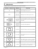
Adjustments
This section provides the adjustment procedures for the 3-way
control valve (FIG. 4-1) and the APW electronic control
system.
Prior to shipment from the manufacturer, control valve
actuators are adjusted (auto-stroked) to ensure that they
properly position the control valve from the fully-open to
the fully-closed positions. In addition, the electronic control
system is adjusted to the set point temperature specified on the
sales order.
It is recommended that the following procedures be performed
to the extent necessary, prior to placing the water heater
into operation. Also, the applicable procedures MUST be
performed following replacement of the control valve or
electronic control system components to ensure that all
parameters are properly set.
2000527529
HANDWHEEL
ELECTRONIC
MODULE
PORT A
PORT AB
VALVE BODY
PORT B
Figure 4-1
3-Way Control Valve
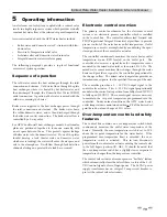
Control valve calibration and status indications
The control valve actuators are self-calibrating for all valve
sizes; therefore, simply proceed as follows to automatically
adjust the valve actuator:
1. Reference FIG. 4-2 and loosen the two (2) captive screws
securing the cover on the electronic module of the
control valve. Remove hand-wheel ring.
CAUTION
As a precaution, ensure that all heating
fluid (hot boiler water) shutoff valves are
fully closed prior to performing any of the
following adjustment procedures.
3-way control valve adjustment
The 3-way control valves used on all APW models are powered
by 24 VAC. For APW applications, each 3-way valve is
controlled by a 0 to 10 VDC signal received from the temperature
controller contained in the electronic control system. A 0 VDC
signal places the control valve in the full bypass position from
port B to port AB (valve shaft up). A 10 VDC signal places the
control valve in the full flow position from port A to port AB
(valve shaft down).
COVER
SCREWS (2)
HANDWHEEL
RING
HANDWHEEL
Figure 4-2
Control Valve Electronics Module - Top View
2. Remove the electronics module cover from the valve to
access the internal components as shown in FIG. 4-3.
DIP SWITCHES
LED
AUTO-STROKE BUTTON
HANDWHEEL
Figure 4-3
Control Valve with Electronics Module Cover
Removed
When external 120 VAC power is properly
connected to the control box, 24 VAC power
is supplied to the control valve when the
control box POWER switch is set to the ON
position. The POWER switch is located on
the front of the control box.
NOTICE
3. Ensure that all three (3) DIP switches shown in FIG. 4-3
are in the OFF (Down) position as shown.
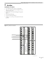
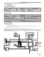
Indirect Plate Water Heater Installation & Service Manual