background image

preparing the wall or ceiling cutout

Confirm there is at least 1" between the final cutout and nearby studs or joints for positioning mounting
hardware.  Temporarily fasten the stiff paper template (supplied) to the wall with thumbtacks. Carefully
trace around the perimeter with a pencil.  Before making the final cutout of the entire hole, first make a
small 4-inch"test" cutout in the center of your penciled outline.  Reach your hand inside to verify that
studs are outside the outline.  This is an important step, since stud finders are not infallible.

To cut the actual hole, first score wallboard with a sharp knife; then use a keyhole saw to complete the
cut.  Remove remaining debris from the edges.  Hold the speaker up to the cutout to make sure it inserts
easily without forcing.

At this point, it is a good idea to secure the speaker wire to a stud near the cutout so its own weight will
not tug on the terminals of the speaker after it is connected.  This will also prevent you from losing the
wire in the wall.  Before attaching the wire, make sure the speaker wire runs through, not around, the
metal mounting bracket.

final installation

1.

Use the supplied cut-out templates to outline the mounting holes to be cut in the wall.  Be sure the
intended hole is square and plumb.
Remove the perforated section out of the center of the template.  Save this section, it will serve as

painting mask if you wish to paint the speaker in the wall.  Use the inside edge of the remaining 
section of the template to mark the hole size

2.

Cut the hole.

3.

Route the speaker wire from the amplifier to the speaker installation location.  Secure the wires to
prevent them from falling into the wall before the speaker is mounted.

4.

Adhesive-backed foam strip-gaskets are supplied with the packing materials.  These will be used to
line the back of the mounting collar flange.  Remove the speaker from the corrugated shipping 
sleeve.  Peel the backing from the foam strip-gaskets and place them along the back of the 
mounting collar flange.  Cut them to size if necessary.  Be sure to butt the strips up against each 
other to prevent possible air leakage.  Once the strips are positioned properly, press them firmly into
place.  NOTE:  this step is not necessary if you are installing the speaker into sheet-rock.  Sheet-rock
is soft enough to compress and naturally seal the gap.

5.

Separate the two wire conductors from each other.  Strip away approximately 1/4” of insulation 
from each of the wire conductors.  Twist the strands together into neat bundles.

6.

Push the positive (+/red) terminal to open the wire hole.  Insert the positive conductor and release 
the terminal to lock the wire into place.  Be sure not to insert the conductor too far causing the 
terminal to lock down on the insulation instead of the wire strands.  Perform this same task for the
negative (-/black) terminal as well.

4

Содержание HT300iw

Страница 1: ...analog and digital systems HT300iw HT400iw HT800iw owner s manual ...

Страница 2: ...ur best record of the date of purchase which is required for warranty service Read and follow all cautions warnings and notes cautions To reduce the risk of electric shock do not remove any parts of the speaker There are no user serviceable parts inside If service is required have it performed by a qualified service professional WARNING To prevent fire or shock hazard do not expose the speakers to...

Страница 3: ...trend Using the most advanced injection molded driver technology available it outperforms all others in its category Attractively styled in a neutral off white finish it can be painted to perfectly match any wall aluminum extrusion mounting side rails The advantage to this design is an incredibly rigid durable mounting system that runs the entire length of the speaker from top to bottom The mounti...

Страница 4: ...ck with your dealer before wiring multiple speaker pairs general mounting suggestions Avoid placing the speaker within two feet 0 6 meters of a corner The acoustic reflections from surfaces near the speakers can detract from the sound quality Do not place the speaker behind heavy fabrics if you cannot see through a fabric you cannot hear through it The in wall speakers are designed for infinite ba...

Страница 5: ...f the template Save this section it will serve as a painting mask if you wish to paint the speaker in the wall Use the inside edge of the remaining section of the template to mark the hole size 2 Cut the hole 3 Route the speaker wire from the amplifier to the speaker installation location Secure the wires to prevent them from falling into the wall before the speaker is mounted 4 Adhesive backed fo...

Страница 6: ... other mounting bracket enters the mounting hole and the speaker is seated on the wall fig 2 fig2 9 Hold the speaker in place in the mounting hole and begin tightening the mounting screws to draw the mounting bracket against the backside of the wall Gradually tighten the screws moving from one to another until the speaker is firmly clamped in place fig 3 fig3 5 ...

Страница 7: ...rille is removed custom painting Paint the speaker frame and grill before mounting to the wall paint grill and frame separately Before painting mask the recessed area of the speaker to completely protect the speaker drivers After painting the grill gently blow through its perforated holes to prevent paint clogging operation checking the system Listen carefully to each speaker If you hear buzzing o...

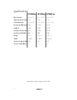
Страница 8: ...0 1 8 7 1 4 x 15 7 8 7 1 4 x 27 1 2 Power range RMS watts 15 80 15 100 15 150 Impedance 4 ohms 8 ohms 4 ohms Frequency response Hz 53 20k 45 20k 40 20k Sensitivity 1W 1M dB 87dB 89dB 91dB Woofer 5 1 4 5 1 4 x 2 5 1 4 x 4 Tweeter 1 dome 1 dome 1 dome Crossover frequency Hz 2 6k 2 4k 2 4k Crossover slope dB oct 12 12 12 Specifications subject to change without notice 7 ...

Страница 9: ...TS OF THIRD PARTIES INCLUDING ITS AUTHORIZED DEALERS OR INSTALLERS Unit must be returned to Directed postage pre paid with bill of sale or other dated proof of purchase bearing the following information consumer s name telephone number and address authorized dealer s name and address and product description Note This warranty does not cover labor costs for the removal and reinstallation of the uni...

Страница 10: ...a Directed Electronics Inc All rights reserved G39556 61 71 03 05 ...

Отзывы: