background image

When removing or installing the grilles, be careful not to brush the woofer's rubber surround or the
tweeter's dome with the edge of the grille. Cutting or tearing the surround or dome will destroy the unit.

Never run wires outside or beneath the vehicle where they can be snagged by road hazards or the moving
parts of the vehicle. Use existing wire channels, sills, panels and molding strips inside the automobile to
hide the wiring for neat appearance and safety.

Make sure your radio/cassette/cd player and or other equipment is turned off while connecting the
speaker terminals. Turn on the various components and slowly advance the volume control ONLY after
checking and double checking all connections.

NOTE:

If the sound is weak or distorted, immediately turn down the volume and see the section entitled

Troubleshooting

.

installation planning

Proper installation planning is the best way to maximize performance. By planning your installation
carefully you can avoid situations where the performance or reliability of your system is compromised.
Your authorized a/d/s/

®

dealer or a/d/s/

®

audio technical support at 1-800-753-0800 x2033 has been

trained to know how to maximize your speakers sonic potential. They are a valuable resource in helping
you with your system design and installation.

amplifier requirements

This speaker system requires a minimum of 45 watts per channel to achieve reasonable listening volumes
in a moving automobile without clipping the amplifier. a/d/s/

®

recommends 150 watts per channel as a

maximum so as not to exceed the thermal or mechanical limitations of the speaker system. Any amplifier
between 45 watts and 150 watts may be used. If you choose to use an amplifier with more than 150
watts use caution as speaker damage may occur at high volume settings. All a/d/s/

®

loudspeakers will

produce reasonable volume levels in the automotive environment using moderate amplifier power.
However, the use of a low powered amplifier to try and attain very high volume levels can lead to
overdriving the amplifier and damaging the speaker system. As a rule, do not turn the volume up above
the point where you hear distortion on musical peaks from either an overdriven amplifier or mechanical
noise from an overstressed speaker. For the best performance and reliability; select an amplifier with
slightly more than the maximum power you are likely to need to generate the desired volume levels. This
margin of reserve power will ensure that the amplifier will not be routinely driven beyond its design limits.

WARNING:

Excessive sound pressure level can permanently damage your hearing. The maximum volume

levels attainable with a/d/s/

®

speakers, combined with high-power amplification, may exceed safe levels

of extended listening.

mounting locations

There are many possible choices of mounting locations. The vehicle factory locations will usually dictate
the woofer mounting position. Because of its small size and multiple mounting options, the tweeter can
virtually go anywhere. a/d/s/

®

uses an unusually low crossover frequency for the tweeter which means you

are not restricted to mounting the tweeter close to the midrange speaker. The tweeter can be mounted
as far as 24" (60 cm) from the midrange speaker without causing adverse effects on the sound quality.
However, better results are usually obtained by locating the tweeters and midranges relatively close to
each other, and by keeping the sound path lengths between the listener and the left and right speakers
as equal as possible.

a/d/s/

®

cannot recommend specific tweeter mounting locations for each vehicle, but in general try to keep

the tweeters as far to the sides of the car as practical. Avoid placing them above ear level unless the
woofers are also above ear level. Place the tweeters in similar locations on both sides of the vehicle. Try a
few locations by just placing the tweeter or taping it in a location and listening to ensure the desired
stereo image and high frequency dispersion are achieved before committing to a location by drilling holes
in the vehicle. You should also experiment with the tweeter phase switch settings to find the most
effective combination of location and phase.

3

Содержание 245ix

Страница 1: ...analog and digital systems 245ix 246ix owner s manual ...

Страница 2: ...30 years of loudspeaker research and development with innovative and timeless industrial design and cutting edge material choices Tuned for precise reproduction of the supplied musical signal they accurately deliver every nuance and detail while retaining the classic a d s sound that has enchanted multiple generations of owners With a minimum of care this high performance component speaker system ...

Страница 3: ...rable typically only available in high quality audiophile home loudspeakers Solid state tweeter protection Advanced protection circuitry provides protection for the tweeter against overpowering or amplifier clipping cautions Study your automobile thoroughly before you drill or cut any holes Take extra care when working near gas tanks gas lines brake or hydraulic lines and electrical wiring Wear ey...

Страница 4: ...me levels can lead to overdriving the amplifier and damaging the speaker system As a rule do not turn the volume up above the point where you hear distortion on musical peaks from either an overdriven amplifier or mechanical noise from an overstressed speaker For the best performance and reliability select an amplifier with slightly more than the maximum power you are likely to need to generate th...

Страница 5: ...if too much power is delivered to the tweeter If activated the tweeter will briefly stop producing sound until the breaker automatically resets Tweeter DC Clip protector These components limit the amount of current delivered to the tweeter if overdriven by either excess amplification or clipped signal from an overdriven amplifier Connections to the amplifier The crossovers are supplied with remova...

Страница 6: ...For wire runs of 50 feet 15 m or less we recommend 16 gauge or larger wire The crossover connector will accept up to 14 gauge wire Polarity and phasing The polarity of the positive negative orientation of the connections for every speaker and amplifier connection must be consistent so all the speakers will be in phase When the polarity of one connection is reversed bass output may be reduced or st...

Страница 7: ...ute the speaker wire from the woofer installation locations to the crossovers Pull the wire through the installation hole and attach the terminals on the ends to terminals connections on the speakers Refer to the speaker wiring section of this manual and the wiring diagrams Push the wire back into the area behind the installation location and be sure it will not interfere with the speaker or get s...

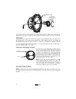
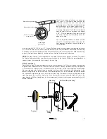
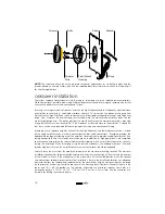
Страница 8: ...eed the tweeter speaker wires through the front center of the woofer where the aluminum bullet was removed As shown in the next illustration Align and thread the coaxial tweeter assembly on the threaded post in the center of the woofer Rotate the coaxial tweeter assembly clockwise until snug Connect the tweeter wires to the tweeter output from the crossover Tweeter Coaxial Extension Tweeter Speake...

Страница 9: ... the bottom of the surface mount cup Screw the cup in place Ensure the mounting screws are driven in straight so the heads sit flush on the cup mounting surface This ensures the tweeter will seat properly in the surface mounting cup The tweeter is then slid into the mounting cup tabs aligned with the mounting slots and turned counterclockwise to lock in place NOTE The mounting cup is also supplied...

Страница 10: ...led surface mounting cup not shown This allows the tweeter to be mounted at an optimum acoustic angle for the listener Follow the same procedure as above to mount and assemble the tweeter in this housing Tweeter mounting Route the wire from the crossover locations to the tweeter locations Pull the wire through the mounting cup and attach crossover wires to the wires from the tweeters Connect the p...

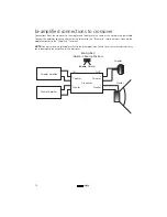
Страница 11: ...ingle amplifier channel used in conventional and bi wired connections Bi amping provides the additional advantage of allowing use of the amplifier s level controls to provide an additional level of fine tuning not possible with the tweeter level switch alone In addition at high power levels a bi amplified connection can help protect the tweeter from amplifier clipping which is more likely to occur...

Страница 12: ...er Insert the prepared wire into the appropriate location see diagram or refer to the crossover circuit board in the connector strip and tighten the screws to secure the wires in place Be sure to note the polarity marking on the circuit board crossover connections and input switch setting Route the wires connected to the input terminals on the crossover network to the power amplifier Connect the w...

Страница 13: ...o the Tweeter In terminals input Connect the woofer amplifier to the Woofer In terminals NOTE You must move the selectable switch to the Bi amp position Failure to set the switch correctly may cause damage to the amplifiers or the crossover Tweeter Woofer Tweeter Amplifer Woofer Amplifer Crossover IN OUT Woofer Tweeter Woofer Tweeter Bi Amplified Switch in Bi amp Position Bi amp Parallel 12 ...

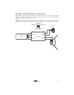
Страница 14: ...Connect the amplifier to the woofer input terminals with another run of wire NOTE You must move the selectable switch to the parallel position Failure to set the switch correctly will not damage the equipment but could interfere with any enhancement of the sound due to bi wiring Tweeter Woofer Amplifer Crossover IN OUT Woofer Tweeter Woofer Tweeter Bi Wired Switch in Parallel Position Bi amp Paral...

Страница 15: ... output Preamp volume set to high exceeding maximum capability of amplifier Check volume or preamp and adjust appropriately Impedance load to amplifier too low Check speaker impedance load if below 1 ohm rewire the speakers to achieve a higher impedance Bi amp Parallel switch set incorrectly for application Set Bi amp Parallel swtich to correct setting see Crossover Connections and Input Switch Se...

Страница 16: ...5 cm 2 5 8 inches 6 67 cm RMSE free 1 18 ohms 0 54 ohms Fs 95 85 Hz 78 08 Hz Re 3 80 ohms 3 85 ohms Res 24 85 ohms 28 55 ohms Qms 5 54 5 70 Qes 0 85 0 77 Qts 0 73 0 68 L1 0 27 mH 0 28 mH L2 0 39 mH 0 42 mH R2 4 01 ohms 3 58 ohms Vas Sd 2 53 liters 5 61 liters Mms 11 46 grams 12 66 grams Cms Sd 241 µm Newton 328 µm Newton Bl Sd 5 56 Tesla M 5 58 Tesla M SPLref Sd 86 0 dB Re 87 2 dB Re Xmax 2 5 mm 2...

Страница 17: ...thermally damaged voice coils are not covered by this warranty but may be replaced at the absolute sole discretion of Directed ALL WARRANTIES INCLUDING BUT NOT LIMITED TO EXPRESS WARRANTY IMPLIED WARRANTY WARRANTY OF MERCHANTABILITY FITNESS FOR PARTICULAR PURPOSE AND WARRANTY OF NON INFRINGEMENT OF INTELLECTUAL PROPERTY ARE EXPRESSLY EXCLUDED TO THE MAXIMUM EXTENT ALLOWED BY LAW AND DIRECTED NEITH...

Страница 18: ...a 2004 Directed Electronics Inc All rights reserved G39206 11 04 04 ...

Отзывы: