background image

                140cc 4 Stroke Petrol Lawn Mower 

AFTER SALES SUPPORT

e-mail: [email protected]

1800 909 909

MODEL: №. 52371 

(toll free)

AFTER SALES SUPPORT

(toll free)

140cc 4 Stroke Petrol Lawn Mower 

e-mail: [email protected]

1800 909 909

MODEL: №. 52371

14

15

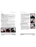
Assembly 

WARNING: Stop the engine and unplug the spark plug before any 

repairs or maintenance operations.
WARNING: DO NOT attempt to start this mower without first adding 

0.6L of SAE 10W-30 engine oil to the Engine. Refer to the oil chart on 

page 16 to confirm the correct oil for various conditions.
WARNING: Do Not attempt to start this mower without the mower 

first being FULLY assembled.
It is necessary to fit the lower handles (6), upper handle and bar (1), 

and the 60L hard catcher (7) to the mower before use.

Attaching the Lower Handles

NOTE:  When preparing for this assembly, slowly and carefully raise the 

handles without pulling or putting any strain on the cable. Ensure the cable 

is not tangled or crossing over.
1.   Remove the lower handle locking knobs (8) from the lower handle 

mounting plates (10). (Fig A)

2.   Position each of the lower handles (6) on the inside of the lower handle 

mounting plate (10),  and locate the circle hole on each end of the lower 

handles (6) onto the large locating pins (one each side) on the lower 

handle mounting plates (10) on each side. (Fig B)

3.   This mower has a 3 height adjustment for the positioning of the handles, 

with the lowest notch positioning the handle bars closer to the ground, 

and the highest notch raising the handle bars up towards the user. (Fig C)

4.   Once you have decided the positioning of the 

handles to suit your mowing height, locate the 

square hole up from the bottom of the lower 

handles (6), and position so they match the 

square notch on the lower handle mounting 

plates (10). (Fig D)

5.   Insert the screw through the lower handle 

square hole, then through the mounting plate 

(10), and secure into position by then screwing 

the lower handle locking knob (8) onto the 

screw on the external side of the  lower handle 

mounting plate (10). (Fig E)

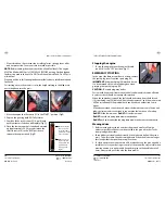
6.   Secure the lower handle locking knob (8)  

until finger tight.

7.   Repeat on the opposite side ensuring both of 

the handle locking knobs are firm and secure.

Attaching the Upper Handles

With the lower handles in position, the upper 

handles and bar (1) can now be secured  

in position.
1.   When the upper handles (1) are in line with 

the lower handles (6) secure them in position 

by pulling the upper handle locking lever (5) 

towards the upper handle bar (1) and locking 

the handle in position (repeat other side). (Fig F)


NOTE: Tension on the upper handle locking 

levers can be adjusted by rotating the lever 

knob.

D.

C.

B.

A.

E.

F.

Содержание 52371

Страница 1: ...140CC 4 STROKE PETROL LAWN MOWER User Manual www 909 com Read all safety warnings and all instructions thoroughly before operating this product ...

Страница 2: ...4 Attaching the Upper Handles 15 Assembly of the 60L Hard Catcher 16 Attaching the 60L Hard Catcher 16 Adding and Checking the oil 17 Fuelling 18 Adjusting the Cutting Height 19 Starting the engine 19 Stopping the engine Emergency Stopping 21 Engine tipping Poor Engine Performance 22 Maintenance Replacing the Blades 23 Air cleaner Maintenance 25 Spark plug 26 Storage andTransporting 27 Service Sup...

Страница 3: ...r including details of starting and stopping and correct use of the Lawn Mower on pages 20 21 as well as the maintenance instructions on pages 23 26 Contents of carton 2 3 Description of symbols The rating plate on your lawn mower may show symbols These represent important information about the product or instructions on its use Conforms to relevant standards for electrical safety and electromagne...

Страница 4: ...ing and gloves away from moving parts Loose clothes jewellery or long hair can be caught in moving parts If devices are provided for the connection of dust extraction and collection facilities ensure that these are connected and properly used Use of these devices can reduce dust related hazards Power tool use and care Do not force the power tool Use the correct power tool for your application The ...

Страница 5: ... do not attempt to start the engine but move the machine away from the area of spillage and avoid creating any source of ignition until the fuel has evaporated and the vapour dispersed Replace all fuel tanks and containers caps securely Substitute faulty silencers Before use always inspect the machine especially the condition of the blades and check that the screws and cutting assembly are not wor...

Страница 6: ...s and objects in the working area Keep children and domestic animals at a safe distance while the mower is in use Maintenance and Storage Keep all nuts bolts and screws tight to be sure the equipment is in safe working condition Regular maintenance is essential for safety and performance Never store the equipment with fuel in the tank inside a building where vapour may reach a flame or a spark or ...

Страница 7: ...e centre to carry out any repairs if necessary If the mower vibrates in an abnormal way take the mower to an authorised service centre 10 11 Check the bolts and nuts regularly Bolts and nuts may vibrate loose over time WARNING Fuel is highly flammable Keep fuel in a jerry can specially made for this purpose Fill the fuel tank with a funnel and outside Do not smoke or use a mobile phone during this...

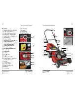
Страница 8: ...60L hard catcher 8 Lower handle locking knob x 2 9 Cable holder clip x 1 10 Lower handle mounting plate with 3 height position 11 Catcher attachment tabs 12 Rear discharge guard 13 8 Height adjustment lever 14 Rear wheels 15 Recoil starter 16 Fuel tank 17 Fuel tank cap 18 Engine 19 Oil filler cap dipstick 20 Spark plug cover Spark Plug located under cover 21 Air filter 22 Air filter cover 23 2 x s...

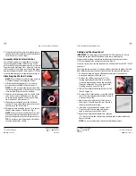
Страница 9: ...ge locating pins one each side on the lower handle mounting plates 10 on each side Fig B 3 This mower has a 3 height adjustment for the positioning of the handles with the lowest notch positioning the handle bars closer to the ground and the highest notch raising the handle bars up towards the user Fig C 4 Once you have decided the positioning of the handles to suit your mowing height locate the s...

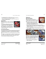
Страница 10: ...r before it has reached maximum capacity otherwise it will decrease the performance of the lawn mower TIP Do not leave grass clippings in the catcher for extended periods of time G H I J Adding and Checking the oil IMPORTANT This lawn mower is packed with NO OIL in the engine Prior to starting the engine Oil MUST be added to the sump of the engine Failure to add sufficient oil will result in damag...

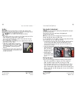
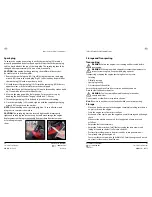
Страница 11: ...ght WARNING Stop the engine and unplug the spark plug before any repairs or maintenance operations The mower has one lever to easily adjust the cutting height There are 8 height settings NOTE Always try to adjust the cutting height of the lawn mower while positioned on the area of grass you plan to mow It is recommended to start on a higher setting and mow a trial area of lawn before deciding on t...

Страница 12: ...osition Fig S EMERGENCY STOPPING In the event the lawn mower does not stop remove the spark plug cover from the spark plug 20 IMPORTANT if the spark plug 20 method is used it is recommended to wear a rubber glove when grasping the spark plug cap 20 CAUTION The spark plug may be hot Persons with heart conditions or any medical condition which can be affected by electric shock should not attempt thi...

Страница 13: ...t If the engine is not running at full speed check the fuel is fresh check the oil level and also inspect under the deck to ensure there is no build up of grass Check the spark plug If the mower continues to underperform take the mower to your nearest an authorised Service Agent T Maintenance Replacing the Blades Note Before making any adjustment or maintenance procedures to the lawn mower ensure ...

Страница 14: ...ecomes worn Replacement blade sets are available for purchase from www extrabattery com au or by calling 1800 909 909 Air Cleaner Maintenance The air cleaner system uses a pleated filter IMPORTANT A dirty air filter 21 will restrict air flow to the carburettor To prevent carburettor malfunction service the air filter 21 regularly Check that the air filter 21 is clean and dry of dirt Filters thick ...

Страница 15: ...ompress the washer CAUTION The spark plug must be securely tightened An improperly tightened spark plug can become very hot and may damage the engine Replacement spark plugs are available from purchase from lawn mower or small engine repair shops AC AB Storage andTransporting Transporting WARNING Ensure the engine is not running and has cooled before transporting WARNING If the engine must be tipp...

Страница 16: ...t throw it in the trash or pour it into the earth Service Support If you have any issues with the operation of your product please take it with a copy of your receipt to one of our National Service Agents for repair A listing of our Service Agents is included with your product however you can also find our most updated listing by visiting powertoolsupport com and clicking on the Service Agent link...

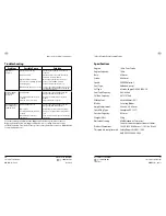
Страница 17: ...cher is not filling up to optimum level Cutting height too low Grass is wet 2 x swing blades 23 are dull or blunt Rear discharge chute 12 is blocked Increase the cutting height using the 8 height adjustment lever 13 Allow the grass to dry before mowing Sharpen or replace the 4 x swing blades 23 Stop mower and clear the rear discharge chute 12 For issues relating specifically to the Briggs and Stra...

Страница 18: ...P 1800 909 909 E info 909 com W www 909 com ...

Отзывы: