background image


3. INSTALLATION 


3.1  Unpacking and start-up 


After  unpacking  retain  all  packing  material  and  fixtures,  as  the  unit  must 
always be transported in its original packaging to avoid damage. 

The manufacturer accepts no responsibility for damage incurred unless the unit 
is correctly packed and transported in this way. 

Remove the 4s2 unit from its packaging. 

The  unit  has  to  be  placed  on  a  level  surface,  away  from  direct  sunlight 
ensuring access to the power switch at the back of the unit. 

Ensure that the vents on the casing are not obstructed. 

The mains voltage selector switch should be checked to ensure that the voltage 
has been set at the correct value. 

Connect  the  unit  to  the  mains  power  supply  and  switch  on  the  switch  I/O  of 
the rear power interface. 

If  the  heater  within  the  unit  is  receiving  power  the  amber  LED  on  the  control 
panel will be illuminated. 

After  switching  on  wait  until  the  amber  LED  light  stops  flashing  (the  set 
temperature is reached and the unit is ready to seal).  


3.2  Voltage Check 


Be sure that the equipment is not connected to the mains power. 


At the rear of the 4s2 is the connection panel with  


Power setting 230/115 Vac and Fuse Holder 


I/O Power Switch 


Mains Power Plug. 

The set voltage is displayed in white on red background on the power setting 
and fuse holder.


Chapter 


3


     8 

Содержание 4s2

Страница 1: ...4s2 Variable Temperature Thermal Sealer foto...

Страница 2: ...references to names or parts are purely casual and are used to illustrate the product described The document is for information only The manufacturer accepts no liability for errors contained herein...

Страница 3: ...Operating Mode 10 4 2 Set Up Stand By Power Down Buzzer 11 5 Basic Functions 12 5 1 Run Mode 12 5 2 Stand By Mode 14 5 3 Power Down Mode 14 5 4 Drawer Locking 14 6 Troubleshooting 15 6 1 Introduction...

Страница 4: ...the operator needs to position the sample plate together with a foil or film on the plate carrier The sealing operation starts once the drawer with the plate carrier has been closed Film and sample pl...

Страница 5: ...wing safety notes This product must only be used in accordance with proper safety standards and procedures together with the instructions included in this manual The sealer has been designed and manuf...

Страница 6: ...the unit is only connected to an earthed supply There are no user accessible or serviceable parts inside the unit Do not remove the unit s cabinet WARNING Hot surface The hot plate can reach temperat...

Страница 7: ...ve humidity 20 80 not condensing SET UP PARAMETERS Sealing temperature OFF or from 120 C to 200 C Step 1 C Default OFF Sealing time up to 10 seconds Step 0 5 seconds Default 3 seconds Stand by cycle n...

Страница 8: ...FICATION 2 1 Sealer Parts Casing 1 Control panel 2 Rear Power Interface 3 Heating element 4 Plate carrier 5 96well PCR Plate Adapter 6 optional Weighted platten 7 Sealing Frame 8 Chapter 2 5 2 1 3 4 5...

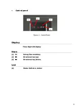
Страница 9: ...Control panel Figure 2 Control Panel Display Three Digit LED display Keys 1 M Set up Run mode key 2 Directional key up 3 Directional key down Led 4 Status Indicator Amber 1 2 3 4 6...

Страница 10: ...2 1 2 Rear Power Interface Figure 3 Rear Power Interface 1 Power Setting 115 230 Vac and Fuse Holder 2 I O Power Switch 3 Mains Power Plug 2 1 3 7...

Страница 11: ...ltage selector switch should be checked to ensure that the voltage has been set at the correct value Connect the unit to the mains power supply and switch on the switch I O of the rear power interface...

Страница 12: ...rewdriver lever out the fuse holder figure 3B 3 Replace the two fuses according to the table below Power Voltage EN 60127 115v 3 15A T 230v 2A T Table 4 Insert the fuse holder keeping the set voltage...

Страница 13: ...see page 20 for recommended sealing temperatures By pressing the M key again the new temperature value is stored and the sealing time can be set next The display shows the symbol t and the last set se...

Страница 14: ...n time can be set next The display shows the symbol P flashing and the last set power down time displayed as hours The power down time is the time after which the heater is switched off automatically...

Страница 15: ...n be loaded onto the standard plate carrier However for easier handling of shallow well plates we recommend to place the standard plate carrier 4ti 0615 inside the adapter for 96well PCR plates option...

Страница 16: ...stop moving An error message will be displayed and a continuous audible beep will be emitted To rectify this and to continue with the sealing process push the drawer in fully until you can a beep If...

Страница 17: ...e stand by function 5 3 Power down Mode If the unit remains idle in stand by mode for a prolonged time the system will go into power down mode and the heating element will be switched off factory set...

Страница 18: ...the low position within a defined time Er5 motor over current Er6 temperature sensor opened or disconnected Er7 open drawer sensor active during elevation movement Er8 platform in low position sensor...

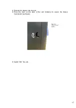
Страница 19: ...supply Do not attempt to clean the unit until it has cooled down to near room temperature Release the lever on the back of the unit counterclockwise see figure The drawer can now be fully removed fro...

Страница 20: ...Reinsert the drawer into the unit Move the lever on the back of the unit clockwise to secure the drawer mechanism see figure Switch ON the unit 17 Figure 8 C Lever in open position...

Страница 21: ...should not be immersed in solvents Do not use acetone or abrasive cleaners No parts are to be autoclaved In case of radioactive spillages it is recommended to use an appropriate cleaning agent For any...

Страница 22: ...ene laminate Clear polyester polypropylene laminate Clear polymer Thin clear polymer Foil laminate Foil 8 3 Plate Carriers Accessories Standard Plate Carrier for skirted plates included product code 4...

Страница 23: ...nd temperature for a 348 Well Plate 4ti 0521 Peel Seal 175 C 3sec 175 C 2sec 4ti 0531 Pierce Seal 175 C 2 5sec 175 C 2sec 4ti 0533 Pierce Seal Strong 175 C 2 5sec 175 C 2sec 4ti 0536 Foil Seal 175 C 2...

Страница 24: ...the sealer 2 Switch off the unit 3 Pull out the drawer 4 Place card board sheet provided between the underside of the drawer and the top of the lifting platform inside the unit 5 Push drawer in Note T...

Страница 25: ...ves note of defects or non conformance during the warranty period the manufacturer will at its option repair or replace the affected product The manufacturer will provide at no additional charge parts...

Отзывы: