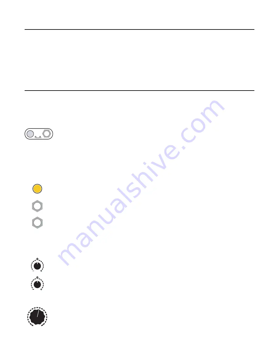
background image

Overview  

The 

Mini PEG 

is a “pingable” envelope generator with the envelope time set by the duration between 

pulses (“pings”). The tempo can be set by tapping the 

Ping

 button, or by patching an external clock into 

the 

Ping 

jack. The ping clock is then multiplied or divided by the amount set by the 

Div/Mult

 knob and 

CV, from /32 to x16. The envelope will be as long as the period of the divided/multiplied clock. Various 

waveshapes can be selected using the 

Shape 

knob and CV. The envelope can also be scaled, inverted 

and offset using the 

Scale 

and 

Offset 

knobs. 

Sending a trigger into the 

Trigger 

jack will produce an envelope. The 

Mini PEG 

can also function as an 

LFO by producing envelopes constantly when the 

Cycle 

button is engaged, or when a gate is held high 

on the 

Cycle 

jack. 

Beginning Patch 

Step 1: Prepare the Mini PEG  

Unplug all cables, turn 

Div/Mult

, and 

Shape

 to center, turn 

Scale

 and 

Offset 

all the 

way up. Make sure 

Cycle

 is off (not lit up). 

Plug the 

ENV OUT 

jack into something you want to modulate — perhaps a filter, or the 

pitch of an oscillator. 

Step 2: Set the ping clock  

Before the 

Mini PEG

 can generate an envelope, you need to supply a ping clock. The 

ping clock is the basic reference that determines the timing of the envelope.  

Tap the 

Ping

 button two or three times, about a second between taps. It's easier to see 

what's going on with a slow envelope. The 

Ping

 button should be flashing white at the 

tempo you tapped. If you give a third tap, the time between taps will be averaged. 

You could also run an external clock into the 

Ping

 jack (when a trigger is received on 

the 

Ping

 jack, the internal tap tempo clock is stopped). 

Step 3: Provide a trigger source 


Like any envelope module, the 

Mini PEG 

will produce an envelope when it receives a 

trigger. Also like many envelope modules, it can be set to self-trigger so that it'll cycle 

without any external trigger. 


Press the 

Cycle

 button (it will light up orange). Notice the red/blue light above the 

ENV 

OUT

 jack starts flashing. The envelope is now running freely, in time with the ping clock. 

Adjust the other module(s) you are running the 

Mini PEG

 into so you can hear the 

modulation.  

You could also turn 

Cycle

 off and run a manual trigger into the 

Trigger 

jack (e.g. try the 

gate output from a sequencer, or a slow LFO, or perhaps a slow clock output from a 

QCD, RCD, or other clock module.) 

Step 4: Adjust the output level 

Adjust the 

Scale

 and 

Offset 

knobs to get a voltage range that works well with whatever 

you're modulating. 

Step 5: Set the Division/Multiplication amount  

Turn the 

Div/Mult

 knob to various settings and watch the 

Ping

 button flash faster or 

slower. Notice how the tempo doesn't change gradually, but instead jumps from speed 

to speed. This is because each speed is an integer multiple or division of the original 

tempo (e.g. three times as fast, or half as slow). You also can modulate this parameter 

with the 

Div CV

 jack at the bottom.  

Page   of 

3

12

Ping

Cycle

Cycle

Trigger

Scale

Offset

6

7

8

=

x2

/2

4

4

5

5

6

7

8

12

16

x16

/32

3

3

Div/Mult

Содержание Mini PEG

Страница 1: ...nd interpolated curves Cycle button and gate jack for looping envelopes Scale knob acts as attenuating inverter for main envelope output Maximum 9 5V peak to peak Offset knob for setting DC offset ranging from 9 4V to 9 4V End of Fall EOF output jack goes high when envelope finishes a fall portion and low when envelope begins a fall portion Jack can also be configured as End of Rise Half Rise or T...

Страница 2: ...ed but incorrectly connecting any module in any system can damage other modules on the power bus Setting up your Mini PEG 2 Overview 3 Beginning Patch 3 Control Details 4 Ping 4 Div Mult 4 Cycle 5 Trigger 5 Shape 5 Scale 5 Offset 5 ENV OUT 6 EOF 6 Maximum and Minimum Clock Times 6 Sync and Async Modes 7 Changing between Sync and Async Mode 7 Cycle Button in Sync and Async mode 7 Modulating Div Mul...

Страница 3: ...ite at the tempo you tapped If you give a third tap the time between taps will be averaged You could also run an external clock into the Ping jack when a trigger is received on the Ping jack the internal tap tempo clock is stopped Step 3 Provide a trigger source Like any envelope module the Mini PEG will produce an envelope when it receives a trigger Also like many envelope modules it can be set t...

Страница 4: ...n if you don t provide any more trigger pulses Note in System Mode you can disable this free running feature thus giving the Mini PEG two external pulses will output just one envelope and then stop See the System Mode section When a gate is received on the Ping jack the tap tempo clock is disabled Conversely when the Ping button is tapped the external clock will be overridden Try tapping a fast te...

Страница 5: ...mes and the selection of waveshapes logarithmic linear exponential While there is a continuous spectrum of waveshapes the range can be divided into three zones The first zone is from fully counter clockwise to around 9 30 Turning the knob clockwise the envelope starts as a ramp up exponential shape and slowly turns to a linear ramp up shape The transition from the first zone to the second zone goe...

Страница 6: ...nd of Rise jack a Half Rise jack or a Tap Clock output jack End of Rise EOR goes high when a fall segment starts and stays high if it stops and goes low when a rise segment starts and stays low if it sustains This jack could be called Envelope is Falling or Stopped Half Rise goes high when the rise portion is half way finished stays high through any sustain period and goes low when the fall portio...

Страница 7: ...When you turn on the Cycle button in Sync mode the envelope will immediately start outputting from the same phase as the ping clock You can imagine this as if the envelope was always running in sync with the ping clock and the Cycle button un mutes it See Figure 2 This can cause some discontinuities but the envelope will always be in sync with the ping clock When you turn Cycle off the output will...

Страница 8: ...so that it starts on the 3 See Figure 8 This can be useful for multi phase outputs e g Quadrature patch Tap Clock Output The EOF jack can be configured to output a tap tempo clock This is done in System Mode see System Mode section When configured as Tap Clock whatever tempo you tap on the Ping jack will be steadily output on the EOF jack Unlike configuring the EOF jack as End of Rise End of Fall ...

Страница 9: ...odule When a firmware update is available it will be posted on 4mscompany com as a WAV file or zipped WAV file Updating Firmware 1 Download the audio firmware file and prepare to play it on your computer or mobile device 2 Set your computer or device volume to maximum both in the system OS controls and also in the audio player application 3 Power off the Mini PEG and unpatch all cables 4 Patch the...

Страница 10: ...urorack module such as the Listen IO between the computer and the Mini PEG Viewing the Firmware Version On power up the Mini PEG displays its firmware version by flashing two colors on the Ping button The first color turns on immediately after power up then the light turns off for a moment and the second color turns on As of this manual printing the latest and only version number is 1 0 Red then W...

Страница 11: ...lse width of the EOF light shows whether the EOF jack outputs gates or triggers When set to gates the EOF light will flash equally on and off When set to triggers the EOF light will flicker briefly on Press the Ping button to toggle 5 Free running Ping The Ping button light will be flashing white or red All other lights will be off The Ping button shows whether the ping clock keeps running after a...

Страница 12: ...30mA Envelope Outputs Maximum voltage range ENV OUT 9 4V to 9 4V Maximum amplitude ENV OUT 9 5Vpp Voltage range 5V OUT 0V to 5V Frequency range 0 1dB DC to 1kHz 1 0dB 2 5kHz 2 0dB 4kHz 12 bit 40kHz sample rate Clock Range Period range 29 16 hours to 250µs 4kHz CV Inputs Div Mult and Shape Voltage range 5V to 5V Gate Inputs Ping Trigger Cycle Rising edge threshold 2 5V Page of 12 12 ...

Отзывы: