background image

Installation  Manual

   |   

VISIX   Network   Camera


10225  Westmoor  Drive,  Suite  300,  Westminster,  CO  80021  |  www.3xlogic.com  |  (877)  3XLOGIC


84  

7.4


Type   IV   Bullet   Camera   

APPLICABLE   CAMERA   MODELS   

This   section   applies   to   the   following   camera   models:   

!


VX-­‐2M-­‐B-­‐RIA   

!


VX-­‐3M-­‐B-­‐RIAWD   

CAMERA   DESCRIPTION   

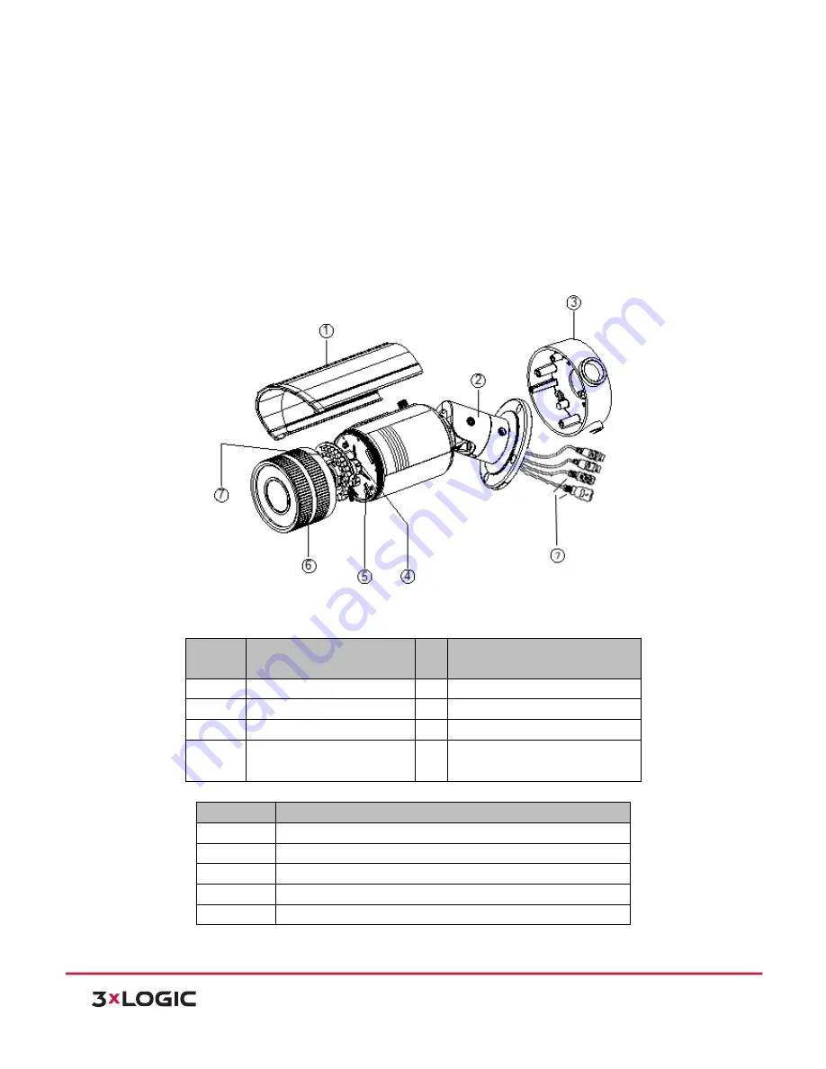
The   overview   of   the   network   bullet   camera   is   shown   below.   Please   note   the   amount   of   cables   included   in   the   
harness   will   vary   between   models.   


Figure  7-­‐17


Overview       


Description  

Table  1-­‐26

No.


Description


No.


Description   

1


Sun   Shield


2


Bracket   

3


Junction   Box


4


Reset   

5


SD   Card   Slot


6


Front   Box   

7


Analog   Video   Output


DC12V;   Power   Interface   

LAN;   Network   Interface   


Alarm  and  Audio  Cable  Description  

Table  1-­‐27

Label   

Definition   

AUDIO   IN


Audio   Input   Interface   

AUDIO   OUT   

Audio   Out   Interface   

D+,   D-­‐:   


RS-­‐485   Interface   

IN,   G


Alarm   Input   Interface   

1A,   1B


Alarm   Output   Interface   


Содержание VSX-1.3MP-MBIR

Страница 1: ...Installation Manual VISIX Network Camera 10225 Westmoor Drive Suite 300 Westminster CO 80021 www 3xlogic com 877 3XLOGIC VISIX Network Camera Installation Manual ...

Страница 2: ...e without notice The manual will be amended if there are any hardware updates or changes DISCLAIMER STATEMENT Underwriters Laboratories Inc UL has not tested the performance or reliability of the security or signaling aspects of this product UL has only tested for fire shock or casualty hazards as outlined in UL s Standard s for Safety UL60950 1 UL Certification does not cover the performance or r...

Страница 3: ...ence 2 This device must accept any interference received including interference that may cause undesired operation EU Conformity Statement This product and if applicable the supplied accessories too are marked with CE and comply therefore with the applicable harmonized European standards listed under the Low Voltage Directive 2006 95 EC the EMC Directive 2004 108 EC the RoHS Directive 2011 65 EU 2...

Страница 4: ...VAC depending on models according to the IEC60950 1 and Limited Power Source standard If the product does not work properly please contact your dealer or the nearest service center Never attempt to disassemble the camera yourself We shall not assume any responsibility for problems caused by unauthorized repair or maintenance To reduce the risk of fire or electrical shock do not expose this product...

Страница 5: ...ronment and do not expose it to high electromagnetic radiation To avoid heat accumulation good ventilation is required for a proper operating environment Keep the camera away from water and any liquid While shipping the camera should be packed in its original packing Improper use or replacement of the battery may result in hazard of explosion Please use the manufacturer recommended battery type NO...

Страница 6: ...NSTALLATION 20 4 1 TYPE I INDOOR DOME CAMERA 20 Applicable Camera Models 20 Camera Description 20 Available Mounts 21 Installation 21 4 2 TYPE II INDOOR DOME CAMERA 27 Applicable Camera Models 27 Camera Description 27 Available Mounts 29 Installation 29 5 MINI DOME CAMERA INSTALLATION 33 5 1 TYPE I MINI DOME CAMERA 33 Applicable Camera Models 33 Camera Description 33 Available Mounts 34 Installati...

Страница 7: ... 62 Camera Description 62 Available Mounts 63 Installation 63 7 BULLET CAMERA INSTALLATION 72 7 1 TYPE I BULLET CAMERA 72 Applicable Camera Models 72 Camera Description 72 Available Mounts 73 Installation 73 7 2 TYPE II BULLET CAMERA 76 Applicable Camera Models 76 Camera Description 76 Available Mounts 77 Installation 77 7 3 TYPE III BULLET CAMERA 78 Applicable Camera Models 78 Camera Description ...

Страница 8: ...9 1 D2 CEILING FLUSH MOUNT VX FM D2 93 9 2 D2 WALL MOUNT ADAPTER VX WM D2 94 9 3 D2 WALL MOUNT WITH JUNCTION BOX VX WMJ D2 95 9 4 MD PENDANT MOUNT VX WM MD 96 9 5 MD WALL MOUNT VX WM MD 97 9 6 OD2 PENDANT MOUNT VX PM OD2 98 9 7 OD2 WALL MOUNT VX WM OD2 99 9 8 OD2 WALL MOUNT WITH JUNCTION BOX VX WMJ OD2 100 9 9 UNIVERSAL CORNER MOUNT VX CM 101 9 10 UNIVERSAL POLE MOUNT VX POLE 102 ...

Страница 9: ...ms Warehouse monitoring systems Surveillance systems for airports railway stations bus stops etc 1 2 Preparations Make sure the device in the package is in good condition and all the assembly parts are included Make sure all the related equipment is powered off during installation Check the specification of the products for the installation environment Make sure the power supply is matched with yo...

Страница 10: ...D Indoor Dome Camera Type I VX 5M D2 RA VSX 5MP D2 360 VSX 2MP D2 RF VSX 3MP D2RF WDR VSX 5MP D2 RF Type II VX 2M D2 RIA VX 3M D2 RIAWD Mini Dome Camera Type I VSX 2MP MVD4 VSX 2MP MVD28 VSX 2MP MVD40 Type II Type A VX 3P28 MD IA VX 3P28 MD IAWI Type B VX 3P4 MD I VX 3P28 MD I Outdoor Dome Camera Type I VSX 3MP ODIR28 VX 3P28 OD I Type II VX 2M OD2 RIAH VX 3M OD2 RIAWD Type III VSX OD2 IRFH Bullet...

Страница 11: ...A DESCRIPTION The overview of Type I Full Body Camera is shown below Figure 3 1 Overview Description Table 1 1 No Description 1 Lens Mount 2 Back Focus Ring 3 SD Card Slot 4 Auto iris Interface 5 10M 100M Self adaptive Ethernet Interface 6 VIDEO OUT Video Output Interface 7 AUDIO OUT Audio Output Interface 8 POWER Power LED Indicator 9 Power Supply Interface 10 MIC IN Audio Input Interface 11 D D ...
Страница 12: ...ce is shown in below Figure 3 2 Auto iris Interface Pins Table 1 2 No DC driven 1 Damp 2 Damp 3 Drive 4 Drive NOTE Power Video and GND pins are used when the auto iris is driven by video Damp Damp Drive and Drive pins are used when the auto iris is driven by DC AVAILABLE MOUNTS Universal Corner Mount 3xLOGIC Product VX CM Universal Pole Mount 3xLOGIC Product VX POLE This camera can also be used wi...

Страница 13: ...the camera with the hole on the bracket arm and use the tightening screw to affix the camera to the bracket 3 Adjust the camera to the desired surveillance angle and tighten the knob on the bracket to secure the camera Figure 3 4 Attach the Camera Installing the Lens 1 Connect the VIDEO OUT interface of the camera to a debugging monitor 2 Adjust the lens focus to obtain the desired image on the mo...

Страница 14: ... 3 5 Install the Lens 3 2 Type II Full Body Camera APPLICABLE CAMERA MODELS This section applies to the following camera models VX 3M AWD CAMERA DESCRIPTION The overview of Type II Full Body Camera is shown below Figure 3 6 Overview 1 The overview of the components and the interface are shown below Figure 3 7 Overview 2 1 2 4 3 5 ...

Страница 15: ...NC Screw Hole 4 Status Indicator 5 Auto iris Interface 6 LAN PoE 7 Power Outlet 8 Reset 9 Micro SD Card Slot 10 Video Out 11 Grounding 12 1A 1B Alarm Out 13 RX TX RS 232 14 D D RS 485 15 IN GND Alarm In 16 Audio Out 17 ABF 18 Audio In NOTE Press and hold RESET for 10s when the camera is powering on or rebooting to restore the default settings including the user name password IP address port No etc...

Страница 16: ...used when the auto iris is driven by video Damp Damp Drive and Drive pins are used when the auto iris is driven by DC AVAILABLE MOUNTS Universal Corner Mount 3xLOGIC Product VX CM Universal Pole Mount 3xLOGIC Product VX POLE This camera can also be used with any standard CCTV Camera bracket for wall and ceiling mount application INSTALLATION Ceiling Mounting Steps 1 Install the ceiling mount to th...

Страница 17: ... directly installed to the camera without plugging the power cable of the auto iris into the auto iris interface 3 Plug the auto iris cable into the auto iris interface Figure 3 11 Install the Lens 4 Align the screw threading on the top of the camera with the hole on the ceiling mount arm and use the tightening screw to affix the camera to the bracket 5 Adjust the surveillance angle a Loosen the p...

Страница 18: ... the Zoom Lever and Focus Lever to obtain the desired image on the monitor Figure 3 12 Install the Camera to the Mount and Adjust the Angle Wall Mounting 1 Install the lens not supplied to the camera and rotate it to fasten it 2 Plug the auto iris cable into the auto iris interface Figure 3 13 Install the Lens 3 Loosen the lock screw on the mount and remove the tilt adjust table from the wall moun...

Страница 19: ...ble 4 Fit the removed tilt adjust table to the camera and secure it with two screws Figure 3 15 Install the Tilt Adjust Table 5 Secure the wall mount to the wall with the supplied expansion screws Figure 3 16 Install the Wall Mount 6 Install the camera to the wall mount and tighten the two lock screws 7 Adjust the surveillance angle Tilt Adjust Table Lock Screw ...

Страница 20: ...8 Adjust the Lens a Connect the VIDEO OUT interface of the camera to the debugging monitor b Adjust the focus lever to obtain the desired image on the monitor Figure 3 17 Adjust the Surveillance Angle Installing the SD Card 1 Insert the SD card to the SD card slot to get it installed 2 Push the inserted SD card slightly to eject it using the spring loaded ejection function Figure 3 18 Install the ...

Страница 21: ...ation 4 1 Type I Indoor Dome Camera APPLICABLE CAMERA MODELS This section applies to the following camera models VX 5M D2 RA VSX 5MP D2 360 VSX 2MP D2 RF VSX 3MP D2RF WDR VSX 5MP D2 RF CAMERA DESCRIPTION Figure 4 1 Overview Description Table 1 5 No Description 1 10M 100M self adaptive Ethernet interface 2 Reset Button 3 AUDIO OUT Audio output interface ...

Страница 22: ... password IP address port No etc AVAILABLE MOUNTS D2 Ceiling Flush Mount 3xLOGIC Product VX FM D2 D2 Wall Mount 3xLOGIC Product VX WM D2 D2 Wall Mount w Junction Box 3xLOGIC Product VX WMJ D2 Universal Corner Mount 3xLOGIC Product VX CM Universal Pole Mount 3xLOGIC Product VX POLE INSTALLATION Ceiling Mounting Steps 1 Optional Use pliers to remove one clip or both clips marked in dotted line in Fi...

Страница 23: ...ng base to the ceiling rotate the back box counterclockwise to secure it to the mounting base use the lock screw to secure the dome camera Figure 4 4 Mounting 4 Loosen the set screws with the hex key supplied to remove the bubble Figure 4 5 Disassembling 1 1 1 1 Drill Template A Screw hole 1 for Mounting Base Hole A for cables routed through the ceiling Code 190600249 ...

Страница 24: ...ect the RCA analog video output to a monitor to view the camera image Loosen the lens set screw to adjust the pan tilt and rotation angle 6 Adjust the focus to obtain the desired image Fasten the lens set screw Figure 4 6 Image Adjusting Figure 4 7 Image Adjusting 7 Reinstall the bubble and tighten the screws Figure 4 8 Reinstall ...

Страница 25: ...ng Base 5 Push the dome camera into the in ceiling mounting base rotate the dome camera 10 degrees counterclockwise and then fasten the lock screws to secure the camera in place Figure 4 10 Camera and Mounting Base 6 Cut a 176 180 mm diameter hole in the ceiling and push the dome camera with in ceiling mounting base into the hole NOTE The thickness of the ceiling should be less than 30mm In ceilin...

Страница 26: ...1 www 3xlogic com 877 3XLOGIC 25 Figure 4 11 Installing 7 It is strongly recommended that you use a safety rope to secure the in ceiling mounting base to the roof Figure 4 12 Safety Rope 8 Fasten the lock screws to secure the dome camera Figure 4 13 Fasten Lock Screws Safety Rope Lock Screws ...

Страница 27: ...eo output with a monitor to view the camera image Loosen the lens set screw and pan tilt or rotate the lens to achieve a satisfactory surveillance angle Adjust the lens focus to obtain the desired image Fasten the lens set screw Reinstall the bubble Figure 4 14 Image Adjusting 10 Install the trim plate with screws to finish the installation Figure 4 15 Trim Plate Installing ...

Страница 28: ...amera APPLICABLE CAMERA MODELS This section applies to the following camera models VX 2M D2 RIA VX 3M D2 RIAWD CAMERA DESCRIPTION The overview of the dome camera is shown below Figure 4 16 Overview The overview of the components and the interface are shown below Figure 4 17 Overview 2 The interfaces on the rear panel are shown below 1 2 3 4 6 8 7 5 ...

Страница 29: ...77 3XLOGIC 28 Figure 4 18 Overview 3 Figure 4 19 Overview 4 Description of Overview 2 3 Table 1 6 No Description No Description 1 Black Liner 2 Bubble 3 Lens 4 BNC Interface 5 Reset 6 Status Indicator 7 Test Serial Port 8 Micro SD Card Slot 9 Adapter Plate 10 Side Outlet Description of Overview 4 Table 1 7 10 9 ...

Страница 30: ...luding the user name password IP address port No etc AVAILABLE MOUNTS D2 Ceiling Flush Mount 3xLOGIC Product VX FM D2 D2 Wall Mount 3xLOGIC Product VX WM D2 D2 Wall Mount w Junction Box 3xLOGIC Product VX WMJ D2 Universal Corner Mount 3xLOGIC Product VX CM Universal Pole Mount 3xLOGIC Product VX POLE INSTALLATION Steps 1 Drill the screw holes and the cable hole according to the supplied drill temp...

Страница 31: ...let 2 Attach the adapter plate to the ceiling with the supplied screws Figure 4 22 Install the Adapter Plate 3 Align the mounting base with the adapter plate and rotate the mounting base counter clockwise to affix it to the adapter plate and then secure it by tightening the lock screw Figure 4 23 Install the Mounting Base Side Outlet Lock Screw ...

Страница 32: ...ent 5 Adjust the focus and zoom a Connect the VIDEO OUT interface of the camera to the debugging monitor b To begin set the iris type to MANUAL c Adjust the No 1 Zoom Lever T W to select a proper angle of view d Adjust the NO 2 Focus Lever F N to obtain the desired image on the monitor e Set the iris type to MANUAL if the environment has stable illumination Set the iris type to AUTO if the environ...

Страница 33: ...nterface and adjust these settings from the PTZ control interface Figure 4 26 Zoom and Focus Adjustment of Electronic Lens 6 Attach the black liner to the dome drive 7 Attach the bubble to the dome drive and rotate to tighten it Figure 4 27 Install the Black Liner and Bubble 8 Tighten the lock screw to complete the installation Figure 4 28 Complete the Installation Black Liner Dome Drive Bubble ...

Страница 34: ...applies to the following camera models VSX 2MP MVD4 VSX 2MP MVD28 VSX 2MP MVD40 CAMERA DESCRIPTION Figure 5 1 Overview Physical Description Table 1 8 No Description 1 Cover 2 Lens 3 Power LED indicator Turns solid red when power is connected 4 Base plate 5 Set screw hole 6 Set screw of lens 7 S L Network status indicator When the network is connected the S LED is solid yellow while the L LED flash...

Страница 35: ...t 3xLOGIC Product VX WM MD MD Pendant Mount 3xLOGIC Prodcut VX PM MD Universal Corner Mount 3xLOGIC Product VX CM Universal Pole Mount 3xLOGIC Product VX POLE INSTALLATION Steps 1 Optional Use pliers to remove the clip marked in dotted line in Figure 5 2 on the side of the back box and then route the cables through the opening instead of the cable hole Figure 5 2 Side Clip 2 Loosen the set screws ...

Страница 36: ... Attach the Camera 4 View the video camera image over the network 5 Loosen the lens set screws Figure 5 5 Loosen the Lens Set Screws 6 Insert the hex key into the hole marked in the picture and rotate the hex key to adjust the panning position and tilting position until the desired surveillance angle is achieved Tighten the set screws ...

Страница 37: ...s the lens of camera has already been factory adjusted to the best image adjust only the panning position and tilting position to achieve the desired surveillance angle 7 Reinstall the cover before viewing so that the image appears as it will when final installation is complete 8 If you have achieved the desired image and surveillance angle finish installation of the cover and tighten the set scre...

Страница 38: ... 877 3XLOGIC 37 Figure 5 8 Install the Cover 5 2 Type II Mini Dome Camera APPLICABLE CAMERA MODELS This section applies to the following camera models Type A VX 3P28 MD IA VX 3P28 MD IAWI Type B VX 3P4 MD I VX 3P28 MD I CAMERA DESCRIPTION OF TYPE II MINI DOME CAMERA TYPE A Figure 5 9 Overview 1 8 4 2 1 3 7 6 ...

Страница 39: ...i Antenna 10 Serial Port Interface 11 Hex Screw 12 MIC 13 RESET WPS Button NOTE Press and hold RESET for 10s when the camera is powering on or rebooting to restore the default settings including the user name password IP address port No etc WPS Setup WPS Wi Fi Protected Setup also known as AOSS or QSS is a computing standard that attempts to allow easy establishment of a secure wireless network Re...

Страница 40: ...on on the camera is 120s The link indicator blinks if the wireless connection is succeeded AVAILABLE MOUNTS MD Wall Mount 3xLOGIC Product VX WM MD MD Pendant Mount 3xLOGIC Prodcut VX PM MD Universal Corner Mount 3xLOGIC Product VX CM Universal Pole Mount 3xLOGIC Product VX POLE INSTALLATION OF TYPE II MINI DOME CAMERA TYPE A Steps 1 Drill the screw holes and the cable hole in the ceiling according...

Страница 41: ...ill Template Adapter Plate 2 Loosen the set screw on the front cover to disassemble the camera with the supplied Allen key Figure 5 13 Disassemble the Camera 3 Attach the adapter plate to the ceiling with the supplied expansion screws Drill Template A 1 1 Hole A for cables routed through the wall Screw hole1 for Mounting Base FRONT Code 194101278 ...

Страница 42: ...template you can skip step 3 and go straight to step 4 4 Attach the dome drive with the supplied PM4x8 screws Figure 5 15 Attach the Dome Drive 5 Connect the power cable network cable and the alarm audio cable NOTE Use pliers to remove the removable part and route the cables via side outlet as shown in Figure 5 16 if no cable hole is drilled in step 1 and connect the corresponding cables Adapter P...

Страница 43: ...he WPS RESET button to adjust the surveillance angle 8 Use the supplied adjusting tool to adjust the pan 30 tilt 0 80 and rotation direction 0 360 Figure 5 17 3 axis Adjustment 9 Tighten the hex screw to lock the camera at the desired surveillance angle 10 Align the front cover to the dome drive and tighten the set screws on the front cover to complete the installation Figure 5 18 Install the Fron...

Страница 44: ...e ceiling with the supplied screws in the ceiling bracket package NOTE The matched ceiling bracket model is DS 1271ZJ 120 and you need to purchases it separately if ceiling bracket mounting is adopted 2 Attach the adapter plate to the ceiling bracket with the supplied PM4x8 screws Figure 5 19 Attach the Adapter Plate 3 Install the dome drive to the adapter plate Figure 5 20 Attach the Dome Drive ...

Страница 45: ...omplete the installation Figure 5 21 Install the Front Cover Wall Bracket Mounting 3xLOGIC Product VX WM MD Steps 1 Install the wall bracket to the wall with the supplied screws in the wall bracket package NOTE The matched ceiling bracket model is DS 1272ZJ 120B and you need to purchases it separately if wall bracket mounting is adopted Figure 5 22 Install Wall Bracket i Attach the adapter plate t...

Страница 46: ...80021 www 3xlogic com 877 3XLOGIC 45 Figure 5 23 Attach the Adapter Plate 2 Attach the dome drive to the wall bracket with the supplied screws Figure 5 24 Attach the Camera 3 Align the front cover to the dome drive and tighten the set screws on the front cover to complete the installation ...

Страница 47: ...Micro SD Card This series of camera supports local storage please refer to the following steps to install the Micro SD card Steps 1 Remove the front cover by loosening the set screws on it Figure 5 26 Remove the Front Cover 2 Insert the Micro SD card to the card slot until you hear a click 3 Optional Slightly push the inserted Micro SD card to uninstall it from the camera ...

Страница 48: ...YPE II MINI DOME CAMERA TYPE B Figure 5 28 Overview Physical Description Table 1 10 No Description 1 Cover 2 Lens 3 Power LED indicator It turns solid red when power is connected 4 Base Plate 5 Set Screw Hole 6 Set Screw of Lens 7 S L Network Status Indicator When the network is connected the S LED is solid yellow while the L LED flashes orange 8 RESET Button 9 Micro SD Card Slot Mirco SD Card ...

Страница 49: ...X WM MD MD Pendant Mount 3xLOGIC Prodcut VX PM MD Universal Corner Mount 3xLOGIC Product VX CM Universal Pole Mount 3xLOGIC Product VX POLE INSTALLATION OF TYPE II MINI DOME CAMERA TYPE B Steps 1 Optional Use pliers to remove the clip marked in dotted line in the figure below on the side of the back box and then route the cables through the opening instead of the cable hole Figure 5 29 Side Clip 2...

Страница 50: ...ter CO 80021 www 3xlogic com 877 3XLOGIC 49 Figure 5 31 Install Micro SD Card 3 Attach the camera to the ceiling with the supplied screws Figure 5 32 Attach the Camera 4 View the video camera image over the network 5 Loosen the lens set screws Figure 5 33 Loosen the Lens Set Screws ...

Страница 51: ...le is achieved Tighten the set screws to lock the angle Figure 5 34 Adjust Panning Position Figure 5 35 Adjust Tilting Position NOTE As the lens of camera has already been factory adjusted to the best image you just need to adjust the panning position and tilting position to get the desired surveillance angle 7 Reinstall the cover before viewing the image so that the image you receive will appear ...

Страница 52: ...Installation Manual VISIX Network Camera 10225 Westmoor Drive Suite 300 Westminster CO 80021 www 3xlogic com 877 3XLOGIC 51 Figure 5 36 Install the Back Box ...

Страница 53: ... the following camera models VSX 3MP ODIR28 VX 3P28 OD I CAMERA DESCRIPTION There are two types of camera appearance for this series of camera according to the different models 1 2 3 4 7 8 9 10 5 6 Figure 6 1 Overview of Type I Camera Description of Type IV Dome Camera Table 1 11 No Description 1 Mounting Base 2 Horizontal Stand 3 Vertical Stand 4 Bubble 5 Network Interface 6 Power Interface 7 IR ...

Страница 54: ... Wall Mount 3xLOGIC Product VX WM OD2 OD Wall Mount w Junction Box 3xLOGIC Product VX WMJ OD2 OD Pendant Mount 3xLOGIC Product VX PM OD2 Universal Corner Mount 3xLOGIC Product VX CM Universal Pole Mount 3xLOGIC Product VX POLE INSTALLATION Ceiling mounting Steps 1 Drill the screw holes on the ceiling according to the drill template Figure 6 2 Drilling Template 2 Loosen the set screws with a hex ke...

Страница 55: ...u can route cables through the side opening on the side of the mounting base Figure 6 5 Side Opening 4 Loosen the tilt lock screws adjust the tilting position in a range of 65 degrees and tighten the tilt lock screws 5 Rotate the black liner to adjust the panning position in a range of 180 degrees until you get the desired surveillance angle Figure 6 6 Surveillance Angle Adjustment Tilt Lock Screw...

Страница 56: ... panning position and tilting position to get the desired surveillance angle 6 Reinstall the bubble and tighten the screws Figure 6 7 Bubble Reinstallation Micro SD Card Installation Steps 1 Loosen the lock screws on the bubble to disassemble the camera Figure 6 8 Disassemble the Camera 2 Insert the Micro SD card to the card slot 3 Optional Push the inserted Micro SD card inside and the Micro SD c...

Страница 57: ...ert the Micro SD Card 4 Re install the bubble and tighten the lock screws Figure 6 10 Install the Bubble 6 2 Type II Outdoor Dome Camera APPLICABLE CAMERA MODELS This section applies to the following camera models VX 2M OD2 RIAH VX 3M OD2 RIAWD CAMERA DESCRIPTION OF TYPE A DOME CAMERA The overview of the outdoor dome camera is shown below ...

Страница 58: ...Installation Manual VISIX Network Camera 10225 Westmoor Drive Suite 300 Westminster CO 80021 www 3xlogic com 877 3XLOGIC 57 Figure 6 11 Overview 1 Figure 6 12 Overview 2 3 1 2 ...

Страница 59: ...CVBS White GND Any Available Auxiliary Monitor Output RS485 Red RS485 Yellow RS 485 Interface ALARMINA Brown ALARMINB Orange GND Any Available Alarm Inputs OUT1A Green OUT1B Blue OUT2A Purple OUT2B Green and White GND Any Available Alarm Outputs LINEIN_R Orange and White LINEIN_L MIC Yellow and White LINEOUT_R Gray LINEOUT_L Light Blue GNDx2 Any Available Audio NOTE LINEIN_L MIC is the camera s mi...

Страница 60: ...lied drill template Figure 6 13 Drill Template 2 Install the mounting base to the ceiling with the supplied screws Figure 6 14 Install the Mounting Base 3 Connect the corresponding power cable network cable audio and alarm cables 4 Install the dome drive to the mounting base Drill Tempalte 1 1 2 2 2 2 3 3 3 3 4 4 4 4 Screw Hole 3 for Mounting Base Hole A for cables routed through the ceiling Code ...

Страница 61: ... camera to adjust the panning angle 0 350 c Push the lens forward and backward to adjust the tilting angle 0 80 d Rotate the lens to adjust the azimuth angle of the camera 0 350 e Tighten the lock screw Figure 6 16 3 axis Adjustment 5 Adjust the Lens a Connect the VIDEO OUT interface of the camera to s debugging monitor b To begin set the iris type to MANUAL c Adjust the No 2 Zoom Lever T W to sel...

Страница 62: ...monitor e Set the iris type as MANUAL if the environment has a stable level of illumination Set the iris type to AUTO if the environment has varying illumination levels Figure 6 17 Adjust the Focus and Zoom 6 Fit the black liner back to the camera 7 Align the bubble to camera and secure it by tightening the screws to complete the installation Figure 6 18 Install the Black Liner and Bubble 2 1 ...

Страница 63: ...d yellow when network is connected 3 ACT Indicator flashes blue when network connection is functioning properly 4 PWR Indicator is solid red when the device is powered on 5 Micro SD slot 6 RESET Reset the camera 7 10M 100M self adaptive Ethernet interface 8 Power supply interface NOTE The extended interface can be connected to alarm input output interface audio input output interface RS 485 interf...

Страница 64: ... Product VX POLE INSTALLATION Ceiling Mounting Steps 1 Drill the screw holes on the ceiling using the supplied drilling template If you need to route the cables from the bottom of the camera cut a cable hole in the ceiling Drilling Template Table 1 15 2 Secure the back box to the ceiling with screws Figure 6 20 Mount Back Box 3 Loosen the set screws with the hex key supplied to remove the bubble r...

Страница 65: ...6 21 Disassembling 4 Install the dome drive to the back box and pull the cables through the cable outlet on the bottom of the back box Figure 6 22 Dome Drive Installing NOTE If you need to pull the cable through the side outlet of the camera please remove the cover and use water proof joints and water proof pipe to route the cables ...

Страница 66: ...le and power cable view the camera image over the network Loosen the lock screws adjust the panning position and tilting position and rotate the lens to achieve the desired surveillance angle fasten the lock screws to lock the camera in place Figure 6 24 Angle Adjusting 6 Reinstall the black liner and bubble to finish the installation Reinstall Table 1 16 Outlet Rotate Pan Tilt Lock Screw ...

Страница 67: ...plied to remove the bubble and remove the black liner Disassembling Table 1 18 3 Rotate the toggle to remove it from the toggle bolt 4 Insert the bolt into the toggle bolt hole on the dome drive and use the screw driver to rotate the bolt slightly but not tightly 5 Reinstall the toggle and push the dome drive to the cable hole on the ceiling with toggle bolts aligned with the screw holes on the ce...

Страница 68: ...e bolt and the toggle will automatically secure the dome drive to the ceiling Figure 6 26 Fasten Toggle Bolt 7 Connecting the network cable and power cable 8 View the camera image over the network 9 Loosen the lock screws to adjust the panning position and tilting position and rotate the lens to get the desired surveillance angle 10 Fasten the lock screws Toggle Bolt Ceiling ...

Страница 69: ...225 Westmoor Drive Suite 300 Westminster CO 80021 www 3xlogic com 877 3XLOGIC 68 Figure 6 27 Angle Adjusting 11 Reinstall the black liner and dome drive to finish the installation Figure 6 28 Complete the Installation Rotate Pan Tilt Lock Screw ...

Страница 70: ...gure 6 29 Drilling Template 2 Secure the back box to the wall with the supplied screws NOTE Position the side cable outlet directly below to prevent moisture from getting inside the camera Figure 6 30 Secure Back box 3 Loosen the set screws with the hex key supplied to remove the bubble remove the black liner Drill Template 1 1 2 2 2 2 3 3 3 3 4 4 4 4 Screw hole 3 for Mounting Base Hole A for cabl...

Страница 71: ...back box NOTE If you need to pull the cable through the cable outlet from the side of the camera please remove the cover and use water proof joints and water proof pipe to route the cables Figure 6 32 Side Cable Routing 5 Connecting the network cable and power cable 6 View the camera image over the network 7 Loosen the lock screws to adjust the panning position and tilting position and rotate the ...

Страница 72: ...or Drive Suite 300 Westminster CO 80021 www 3xlogic com 877 3XLOGIC 71 8 Fasten the lock screws Figure 6 33 Angle Adjusting 9 Reinstall the black liner and bubble to finish the installation Figure 6 34 Complete the Installation Rotate Pan Tilt Lock Screw ...

Страница 73: ...era Installation 7 1 Type I Bullet Camera APPLICABLE CAMERA MODELS This section applies to the following camera models VSX 2MP BIR RF VSX 3MP BIR RF CAMERA DESCRIPTION Two types of camera rear panel are shown in Figure 4 7 and Figure 4 8 Choose the right figure according to your purchased product Figure 7 1 Overview Figure 7 2 Overview ...

Страница 74: ...AUDIO IN G Audio input interface AUDIO OUT G Audio output interface AVAILABLE MOUNTS Universal Corner Mount 3xLOGIC Product VX CM Universal Pole Mount 3xLOGIC Product VX POLE These cameras have a built in mount for wall and ceiling mount applications INSTALLATION Steps 1 Attach the mounting base to the wall Figure 7 3 Attach the Mounting Base 2 Attach the mounting bracket with the camera to the mo...

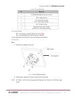
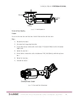
Страница 75: ...slightly NOTE Please loosen the screws slightly until you can adjust the camera and do not remove the screws from the bracket 5 Adjust the camera to the desired surveillance angle and then tighten the screws on bracket to secure the camera Figure 7 4 Adjust Monitoring Angle 6 Loosen the lock screw on the sun shield and slide the sun shield until you can remove it Remove the sun shield Rotation Scr...

Страница 76: ... 3XLOGIC 75 Remove the Sun Shield Table 1 21 7 Rotate to remove the front cover from camera and adjust the lens to get a clear image Adjust the Lens Table 1 22 8 Attach the lens reinstall the front cover and the sun shield to finish the installation Figure 7 5 Complete the Installation Front Cover Adjust the Lens ...

Страница 77: ... Type II Bullet Camera APPLICABLE CAMERA MODELS This section applies to the following camera models VSX 1 3MP MBIR VX 3P28 MD I VX 3P4 MD I CAMERA DESCRIPTION Figure 7 6 Bullet Camera Overview Description Table 1 23 No Description 1 Sun Shield 2 Back Box 3 Grounding Screw 4 Adjustable Bracket 5 Mounting Base 6 Reset 1 2 3 4 5 6 ...

Страница 78: ...duct VX POLE These cameras have a built in mount for wall and ceiling mount applications INSTALLATION Steps 1 Attach the drill template on the wall Figure 7 7 Attach the template 7 Secure the camera to the ceiling with the supplied expansion screws Figure 7 8 Secure the Camera to the Ceiling 8 Adjust the Lens a Loosen the adjustable nut on the bracket b Adjust the panning angle 0 360 of the camera...

Страница 79: ...ghten the adjustable nut to complete the installation 3 axis Adjustment Table 1 24 7 3 Type III Bullet Camera APPLICABLE CAMERA MODELS This section applies to the following camera models VX 3PV B I CAMERA DESCRIPTION The overview of the network bullet camera is shown below Please note the VX 3PV B I will only feature the power and network interface cables Figure 7 9 Overview Adjustable Nut T Direc...

Страница 80: ...rebooting to restore the default settings including the user name password IP address port No etc AVAILABLE MOUNTS Universal Corner Mount 3xLOGIC Product VX CM Universal Pole Mount 3xLOGIC Product VX POLE This line of cameraa have a built in mount for wall and ceiling mount applications INSTALLATION SD Card Installation Steps 1 Loosen the lock screw on the sun shield to slide the sun shield accord...

Страница 81: ...amera 4 Insert the Micro SD card into the Micro SD card slot 5 Rotate the front cover clockwise to install the sun shield according to the arrow direction as shown in Figure 7 11 right Figure 7 11 Install the SD Card 6 Slide the sun shield according to the arrow direction as shown in Figure 7 12 left 7 Tighten the lock screw on the sun shield Lock Screw ...

Страница 82: ...lied to the wall where the camera is to be mounted 2 Drill screw holes in the wall according to the No 1 hole of the drill template Figure 7 13 Drilling Holes in the Wall 3 If you need to route cables through the wall or ceiling cut a cable hole according to the drill template Skip this step if you want to route the cables on the surface of the ceiling 4 Route the cables of the camera 5 Secure the...

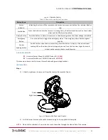
Страница 83: ... lock screw 1 2 Adjust the panning position of the camera The adjusting range is from 0 degrees to 360 degrees 3 Tighten the lock screw 1 Tilt Adjustment Steps 1 Loosen the lock screw 2 2 Adjust the tilting position of the camera The adjusting range is from 0 degrees to 90 degrees 3 Tighten the lock screw 2 Rotation Adjustment Steps 1 Loosen the lock screw 3 2 Rotate the rotation position to adjus...

Страница 84: ...ue and focus value Steps 1 Disassemble the camera 2 View the camera image using the monitor 3 Loosen the zoom lever and move the lever between T Tele and W Wide to obtain the desired angle of view 4 Tighten the zoom lever 5 Loosen the focus lever and move the screw between F Far and N Near to obtain the optimum focus 6 Tighten the focus lever 7 Assemble the camera Figure 7 16 Zoom and Focus Adjust...

Страница 85: ...a is shown below Please note the amount of cables included in the harness will vary between models Figure 7 17 Overview Description Table 1 26 No Description No Description 1 Sun Shield 2 Bracket 3 Junction Box 4 Reset 5 SD Card Slot 6 Front Box 7 Analog Video Output 7 DC12V Power Interface LAN Network Interface Alarm and Audio Cable Description Table 1 27 Label Definition AUDIO IN Audio Input Int...

Страница 86: ... ceiling mount applications INSTALLATION Steps 1 Drill four screw holes in the wall according to the No 2 holes of the supplied drill template Figure 7 18 Drill Template 2 Drill one cable hole according to the sign shown on the drill template NOTE If you want to route the cables through the side of the junction box you can skip this step 3 Secure the junction box to the wall with the expansion scr...

Страница 87: ...bles through the side outlet of the junction box to the surface of the ceiling if there is no cable hole drilled on the ceiling 5 Hook the camera to the junction box with the safety rope 6 Tighten the screws to attach the camera to the junction box Figure 7 20 Attach the Camera to the Junction Box 7 Adjust the camera to the desired surveillance angle and then tighten the screws on bracket to secur...

Страница 88: ...tall a water proof rubber case purchased separately to the foldable position of the bracket if a water proof application is desired 8 Loosen the lock screw on the sun shield and remove the sun shield 9 Rotate to remove the front box from camera and adjust the zoom lever and focus lever to get a clear image Figure 7 22 Lens Adjustment 10 Reinstall the front box and the sun shield to finish the inst...

Страница 89: ...mera Installation 8 1 Type I Cube Camera APPLICABLE CAMERA MODELS This section applies to the following camera models VSX 1 3MP PIR1 CAMERA DESCRIPTION The overview of the network cube camera is shown below Figure 8 1 Overview Figure 8 2 Overview 2 Description Table 1 28 No Description 1 IR LED 1 2 3 4 5 6 7 8 9 10 11 12 14 15 16 13 ...

Страница 90: ...t 13 Alarm In Out GND Audio Out Interface 14 Power supply interface 15 10M 100M self adaptive Ethernet interface PoE 16 WPS Wi Fi Protected Setup Button NOTE Press and hold RESET for 10s when the camera is powering on or rebooting to restore the default settings including the user name password IP address port No etc WPS Configuration A wireless router with the WPS function is required Refer to th...

Страница 91: ...he emergency alarm The emergency alarm has the highest priority Stream Sending Switch Switch for the video stream transmitting Press the button to stop or start video stream sending When the video stream is stopped you can t see the live view or get the record stream on the remote client or web browser AVAILABLE MOUNTS Universal Corner Mount 3xLOGIC Product VX CM Universal Pole Mount 3xLOGIC Produ...

Страница 92: ...sponding power cable and the network cable through the drilled cable hole Or pull the cable through the side outlet of the camera 5 Reinstall the right cover and fixator Figure 8 6 Reinstall the cover and Fixator 6 3 axis Adjustment a View the camera image over the network b Loosen the lock nut 1 to adjust the panning position and tilting position c Fasten the lock nut 1 d Loosen the lock nut 2 to...

Страница 93: ...Installation Manual VISIX Network Camera 10225 Westmoor Drive Suite 300 Westminster CO 80021 www 3xlogic com 877 3XLOGIC 92 Figure 8 7 Adjust the Camera Lock Nut 1 Pan Tilt Lock Nut 2 Rotation ...

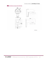
Страница 94: ...Installation Manual VISIX Network Camera 10225 Westmoor Drive Suite 300 Westminster CO 80021 www 3xlogic com 877 3XLOGIC 93 9 Mount Schematics 9 1 D2 Ceiling Flush Mount VX FM D2 ...

Страница 95: ...Installation Manual VISIX Network Camera 10225 Westmoor Drive Suite 300 Westminster CO 80021 www 3xlogic com 877 3XLOGIC 94 9 2 D2 Wall Mount Adapter VX WM D2 ...

Страница 96: ...Installation Manual VISIX Network Camera 10225 Westmoor Drive Suite 300 Westminster CO 80021 www 3xlogic com 877 3XLOGIC 95 9 3 D2 Wall Mount with Junction Box VX WMJ D2 ...

Страница 97: ...Installation Manual VISIX Network Camera 10225 Westmoor Drive Suite 300 Westminster CO 80021 www 3xlogic com 877 3XLOGIC 96 9 4 MD Pendant Mount VX WM MD ...

Страница 98: ...Installation Manual VISIX Network Camera 10225 Westmoor Drive Suite 300 Westminster CO 80021 www 3xlogic com 877 3XLOGIC 97 9 5 MD Wall Mount VX WM MD ...

Страница 99: ...Installation Manual VISIX Network Camera 10225 Westmoor Drive Suite 300 Westminster CO 80021 www 3xlogic com 877 3XLOGIC 98 9 6 OD2 Pendant Mount VX PM OD2 ...

Страница 100: ...Installation Manual VISIX Network Camera 10225 Westmoor Drive Suite 300 Westminster CO 80021 www 3xlogic com 877 3XLOGIC 99 9 7 OD2 Wall Mount VX WM OD2 ...

Страница 101: ...Installation Manual VISIX Network Camera 10225 Westmoor Drive Suite 300 Westminster CO 80021 www 3xlogic com 877 3XLOGIC 100 9 8 OD2 Wall Mount with Junction Box VX WMJ OD2 ...

Страница 102: ...Installation Manual VISIX Network Camera 10225 Westmoor Drive Suite 300 Westminster CO 80021 www 3xlogic com 877 3XLOGIC 101 9 9 Universal Corner Mount VX CM ...

Страница 103: ...Installation Manual VISIX Network Camera 10225 Westmoor Drive Suite 300 Westminster CO 80021 www 3xlogic com 877 3XLOGIC 102 9 10 Universal Pole Mount VX POLE ...

Отзывы: