Installation Manual
|
VISIX Network Camera
10225 Westmoor Drive, Suite 300, Westminster, CO 80021 | www.3xlogic.com | (877) 3XLOGIC
47
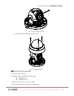
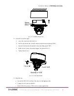
Figure 5-‐27
Install and Uninstall Micro SD Card
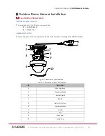
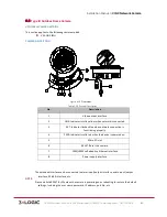
CAMERA DESCRIPTION OF TYPE II MINI-‐DOME CAMERA (TYPE B)
Figure 5-‐28
Overview
Physical Description
Table 1-‐10
No.
Description
1
Cover
2
Lens
3
Power LED indicator, It turns solid red when power is connected.
4
Base Plate
5
Set Screw Hole
6
Set Screw of Lens
7
S & L: Network Status Indicator.
When the network is connected, the “S” LED is solid yellow, while
the “L” LED flashes orange.
8
RESET Button
9
Micro SD Card Slot
Mirco SD Card


