


Install the device on the wall and tighten the screw.
Step 5
Installation ends.
【
Wall-mounted Device Disassembling
】
Power off the device.
Step 1
Hold the device steadily and screw out the screw in
Step 2
the wall.
Take out the device, disassembling ends.
Step 3
Notice Before Powering on:
Power ON operation: First insert the power supply
terminal block into the device power supply interface,
then plug the power supply plug contact and power on.
Power OFF operation: First, remove the power plug,
then remove the wiring section of terminal block. Please
pay attention to the above operation sequence.
【
Power Supply Connection
】
PoE power supply
The WAN port of this device supports 48VDC PoE power
receiving, which conforms to IEEE802.3af/at standard.
12~48VDC power supply
This device provides 1 DC power input which is
3-pin 5.08mm pitch terminal block with
waterproof plug, the power supply supports
non-polarity. Power supply range: 12
~
48VDC. The pin
definitions of power supply are shown as follows:
PIN
1
2
3
Description
V-
FG
V+
【
Reset Button Setting
】
The device provides 1 RESET button that can be used
to reboot the device and restore factory defaults. Press
the RESET button for 1~2s and release it, and the device will
restart automatically; Press and hold the RESET button for 5s
and release it, and the device will automatically restore the
factory defaults.
【
Checking LED Indicator
】
The device provides LED indicators to monitor its operating
status, which has simplified the overall troubleshooting
process. The function of each LED is described in the table
below:
LED
Indicate Description
RUN
ON
The device is powering on or the
device is abnormal.
Blinking
The device is running normally
OFF
The device is powered off or the
device is abnormal.
2.4G
ON
2.4G wireless signal is on.
Blinking
2.4G wireless signal is
transmitting data
OFF
2.4G wireless signal is running
abnormally or turned off
5G
ON
5G wireless signal is on.
Blinking
5G wireless signal is transmitting
data
OFF
5G wireless signal is running
abnormally or turned off
WAN /
LAN
ON
The Ethernet interface has
established an active network
connection
Blinking
The Ethernet interface is in a
network activity state.
OFF
The Ethernet interface has not
established an active network
LED
Indicate
Description
connection.
The indicators are all off,
indicating that no bridge has been
established.
One indicator is on. It means
2.4G/5G signal at the opposite
end is weak
Two indicators are on. It means
2.4G/5G signal at the opposite
end is normal
All indicators are on. It means
2.4G/5G signal at the opposite
end is strong
【
Logging in to WEB Interface
】
This device supports WEB management and configuration.
Computer can access the device via device LAN port. The
way of logging in to device’s configuration interface via IE
browser is shown as below:
Configure the IP addresses of computer and the
Step 1
device to the same network segment, and the
network between them can be mutually accessed
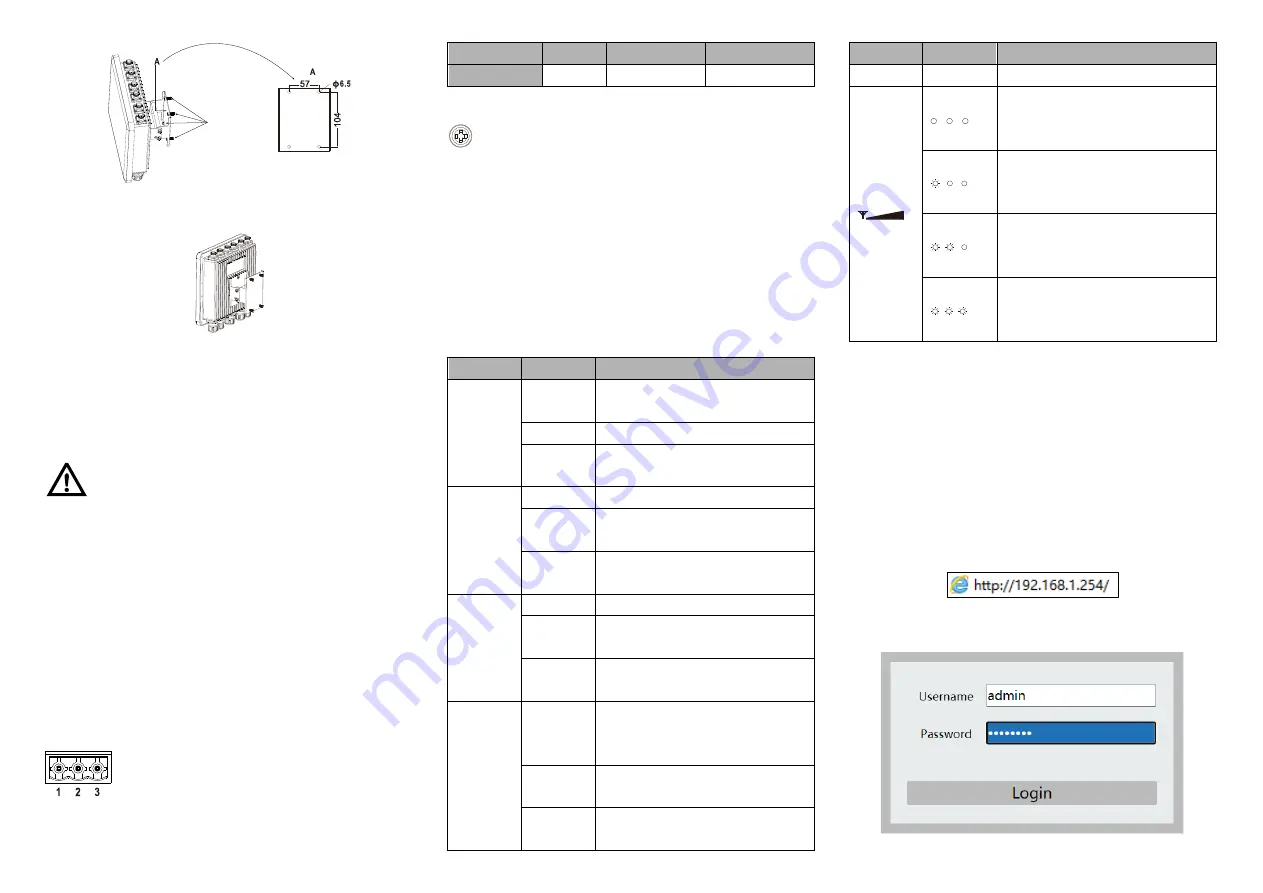
Enter device’s IP address in the address bar of the
Step 2
computer browser.
Enter device’s username and password in the login
Step 3
window as shown below.
Click “Login” button to login to the WEB interface of
Step 4


