background image

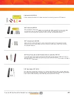
To use the 3M Heat Trace Bill of Materials Tool, visit 

3M.ca/HeatTrace

36

Junction boxes:

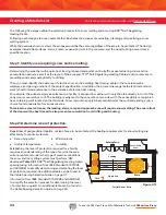
 KSR™ Self-Regulating Heating Cable power connection and end termination points must be located 

inside suitable junction boxes located above the moisture line. Depending on the size of the junction box, several power 

connections and/or end terminations can be located within the same box.

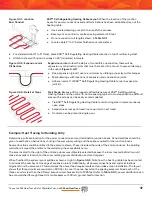
• Protect heating cable with rigid metallic conduit (one cable per conduit) between junction box and area being heated
• Extend conduit (equipped with bushings on each end) a minimum of 12" into slab

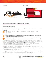
A typical junction box and conduit assembly is shown in 

Figure 3.4.1

.

Note: When calculating the amount of KSR™ Self-Regulating Heating Cable required based on the square footage of the area, allowances should be included for making connections within junction boxes 

and for any expansion joint kits necessary to complete the layout.

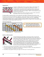
The total operating load of a KSR™ Self-Regulating Heating Cable Snow and Ice Melting System is dependent on the 

supply voltage and the total footage of cable which will be energized. To determine the total operating load, use the 

following amps per foot multipliers:

By inserting the appropriate values into the following formula, the total load of the snow and ice melting system can  

be determined.
As the example facility will have 208 Vac, single-phase, four-wire available, KSR-2 cable is selected. To optimize  

the circuit length potential, the branch circuit breakers will be sized to reflect the layout of the cable (see Step 4 


for cable layout).

Design step 4: specify locations for power connections/end terminations and layout cable on 

scaled drawing

Total KSR™ Self-Regulating Heating Cable required for area in ft

2 x (12 ÷ S) 

and substituting values for the design example:

Total KSR™ Self-Regulating Heating Cable required = 600 ft2 x (12 ÷ 9)

the total footage of cable can be estimated:

Total KSR™ Self-Regulating Heating Cable required = 800 linear feet (plus allowance from Note 2)

Using Formula 3.2:

Pt = Lt x If x E

and substituting values for the design example:

Pt = 840 ft x 0.12 amps/ft x 208 Vac

the total kilowatt demand for the system can be estimated:

Pt = 21 kw

Using Formula 3.1: Putting the Formula to Work

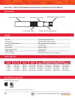
    KSR-2 @ 208-240 Vac draws 0.12 amps/foot

Table 3.3.1: Cable Selection

Catalogue Number

Start-Up  

Temperature

Operating Voltage

Installation Method

Maximum Circuit Length vs. Breaker Size

15 Amp

20 Amp

30 Amp

40 Amp

KSR-2

-18°C (0°F)

208 Vac

Direct burial

 80 ft (24 m) 105 ft (32 m) 160 ft (49 m)

210 ft (64 m)

KSR-2

-18°C (0°F)

240 Vac

Direct burial

85 ft (26 m) 110 ft (34 m)

170 ft (52 m)

225 ft (69 m)

KSR-2

-7°C (20°F)

208 Vac

Direct burial

85 ft (26 m) 110 ft (34 m)

165 ft (50 m)

220 ft (67 m)

KSR-2

-7°C (20°F)

240 Vac

Direct burial

90 ft (27 m) 120 ft (37 m)  180 ft (55 m)

225 ft (69 m)

Содержание TTS-5-1-OJ

Страница 1: ...To use the 3M Heat Trace Bill of Materials Tool visit 3M ca HeatTrace 1 3M Self Regulating Heat Tracing Cables Application Guide...

Страница 2: ...tep 4 choose TTS Self Regulating Heating Cable installation accessories 16 Tips 16 17 Thermostatic Control 17 18 TTS Self Regulating Heating Cable Pipe Freeze Protection Data Sheet 18 19 Roof and Gutt...

Страница 3: ...ating a Materials List 32 Step 1 identify area requiring snow and ice melting 32 Step 2 determine level of protection required 32 33 Step 3 determine length of cable required and circuit lengths 33 34...

Страница 4: ...tance of the heating element increases This causes the heat output of the cable to decrease As the temperature of the heating matrix increases the resistance of the heating matrix increases This is a...

Страница 5: ...ances Copper grounding braid serves as a safety conductor The cable is quipped with an outer protective jacket Benefit the cable can be cut to any desired length without changing TTS and KSR Self Regu...

Страница 6: ...e Bill of Materials Tool visit 3M ca HeatTrace 6 1 Pipe Freeze Protection Legend 2 Roof and Gutter Snow and Ice Melting 3 Surface Snow and Ice Melting 1 1 2 2 2 2 3 3 3 3 3 3M Self Regulating Heat Tra...

Страница 7: ...To use the 3M Heat Trace Bill of Materials Tool visit 3M ca HeatTrace 7 2 2 2 2 2 3 3 3 3...

Страница 8: ...To use the 3M Heat Trace Bill of Materials Tool visit 3M ca HeatTrace 8 Pipe Freeze Protection...

Страница 9: ...s a small project or a complex network designing an electric heat trace system is easy with TTS Self Regulating Heating Cable Please refer to the TTS Self Regulating Heating Cables materials guide for...

Страница 10: ...n gland kit w o junction box 2 ECA 1 SR SP Power connection kit with metallic junction box 2 PCA 1 SR Power connection kit with non metallic junction box 4 PCS 1 SR T splice kit with non metallic junc...

Страница 11: ...To use the 3M Heat Trace Bill of Materials Tool visit 3M ca HeatTrace 11 4 5 6 7 9 1 8 3 2...

Страница 12: ...otection of metallic and non metallic pipes by replacing the heat lost through the thermal insulation into the air Whether the application is a small project or a complex network of piping and equipme...

Страница 13: ...ing Heating Cable Using the pipe diameter insulation thickness and minimum expected ambient find the recommended heating cable using Selection Chart 1 2 1 Metallic Piping on page 14 or Selection Chart...

Страница 14: ...One Pass TTS 8 One Pass TTS 8 One Pass TTS 8 One Pass TTS 8 Two Passes TTS 8 Two Passes TTS 8 Two Passes TTS 8 Two Passes TTS 10 Contact 3M Two Passes TTS 8 Contact 3M Contact 3M Selection Chart 1 2...

Страница 15: ...1 2 3 4 6 8 10 12 14 1 1 5 2 1 1 1 4 1 1 2 2 2 1 2 3 4 6 8 10 12 14 1 1 1 4 1 1 2 2 2 1 2 3 4 6 8 10 12 14 1 Non metallic Piping Selection Chart 1 2 2 Non metallic Piping Additional considerations for...

Страница 16: ...available voltages gathered as part of Step 1 TTS Self Regulating Heating Cable intended for use on 110 120 Vac will have a catalogue number followed by a 1 i e TTS X 1 TTS Self Regulating Heating Cab...

Страница 17: ...10 50 18 0 29 20 40 40 240 73 170 52 150 46 135 41 320 98 225 69 200 61 180 55 405 123 340 104 305 93 275 84 405 123 405 123 405 123 365 111 Table 1 3 2 Table 1 3 3 Example Continuing with the first e...

Страница 18: ...n line can be looped double passed on the branch line This eliminates the need to install a T splice kit 4 What to do when all heating cable power connection points need to be secured to the piping He...

Страница 19: ...ewall sensing Each method has its own benefits and various options are available within each method Ambient Sensing An adjustable thermostat designed for mounting in an exposed environment senses the...

Страница 20: ...s 110 120 or 208 240 vac Max Maintenance temperature 65 C 150 F Max Continuous exposure temperature power off 85 C 185 F Minimum installation temperature 51 C 60 F Minimum bend radius 32 mm 1 25 T rat...

Страница 21: ...0 1 Circuit Breaker Size Cable Type Start Up Temp 30 A 20 A 15 A C F 40 A 10 50 18 0 29 20 40 40 180 55 155 47 140 43 125 38 240 73 205 62 185 56 165 50 285 87 285 87 275 84 250 76 285 87 285 87 285 8...

Страница 22: ...To use the 3M Heat Trace Bill of Materials Tool visit 3M ca HeatTrace 22 Roof and Gutter Snow and Ice Melting...

Страница 23: ...on is a small project or a complex network designing an electric heat trace system is easy with TTS Self Regulating Heating Cables Please refer to the basic components section for roof and gutter snow...

Страница 24: ...ET 4S End termination kit HS PBSK Inline splice with heat shrink HS TBSK T splice with heat shrink Installation accessories 3 AL 20L 3M Aluminum Tape 2 X 150 in gutter 4 CL Caution labels 25 per pack...

Страница 25: ...or heavy levels based on the variables below If any variable falls into the heavy category plan the system for heavy accumulation to ensure adequate protection for the building Should weather conditio...

Страница 26: ...ing Cables circuit length If breaker size will be dictated by heating cable requirements determine the optimal TTS Self Regulating Heating Cables circuit lengths based on the project size and cable la...

Страница 27: ...cross to the spacing pitch column that corresponds to the roofing material The number where the row and column intersect is the multiplier for that application You then need to multiply this number by...

Страница 28: ...ect the row with the corresponding overhang distance and follow across to the multiplier that matches the level of protection desired After selecting a multiplier read the corresponding spacing pitch...

Страница 29: ...lied by installer 2 CL Electric Heat Tracing caution labels peel and stick to junction boxes breaker panels and control panel s or as required by code or specification 3 RG CMC cable mounting clips se...

Страница 30: ...the circuit before connecting to power End of Circuit Termination TTS Self Regulating Heating Cables require the ET 4S end cap for terminating the end of the circuit Note T rating is per the 1996 NEC...

Страница 31: ...To use the 3M Heat Trace Bill of Materials Tool visit 3M ca HeatTrace 31 Surface Snow and Ice Melting...

Страница 32: ...y approved for direct burial KSR Self Regulating Heating Cables withstand harsh installation environments Building entrance and exit locations Ramps and accessibility routes Stairs and footpaths Certi...

Страница 33: ...le The severity of weather in which the system must perform is of primary significance Therefore it is important to establish a performance level1 as the amount of materials and power requirements are...

Страница 34: ...t tracing For example the public employee entrance to a facility is exposed to weather with only the area directly in front of the entry doors covered by a roof The building is adjacent to the concret...

Страница 35: ...onditions ambient temperatures between 6 C 20 F and 1 C 34 F with wind speeds of 5 to 24 km h 15 mph Should the ambient temperature fall below 6 C 20 F during the snowstorm some snow accumulation coul...

Страница 36: ...tem can be determined As the example facility will have 208 Vac single phase four wire available KSR 2 cable is selected To optimize the circuit length potential the branch circuit breakers will be si...

Страница 37: ...entrance doors was ultimately selected because the room located behind it would make an excellent location for the snow melting power distribution and control panel When finished the system layout wi...

Страница 38: ...for assistance at 3Menergysolutions mmm com Example Because the facility will be occupied during normal business hours the system is to be controlled automatically To accomplish this an STC DS 2C sno...

Страница 39: ...in the Cable Spacing Selection Guide chart show the calculated percentage of snowfall hours that a surface will remain clear of snow when a predetermined level of heating is installed This method is u...

Страница 40: ...fault protection required Data sheet KSR Self Regulating Heating Cable for Surface Snow and Ice Melting Silicone Rubber Outer Jacket Nickel Plated Copper Bus Wires Tinned Copper Braid Semiconductive...

Страница 41: ...inless steel pipe attachment bands Heater cable grommets 3 power connection boots TBX 3L RTV adhesive Wire fasteners and grounding splice lug 3M Non Metallic Power Connection Kit PCA 1 SR Designed for...

Страница 42: ...de visual indication of an energized heating circuit The DE B utilizes a high intensity green LED assembly for superior day or night visibility Type 4X pipe mounted fitting with locking splice cover s...

Страница 43: ...cap Both power and end terminations must be made in UL listed or CSA Approved junction boxes End Boot for DE B SCTK 1D Splice connection termination kit includes power boots wire spring connectors RTV...

Страница 44: ...ustable temperature trigger set point from 1 C to 7 C 34 F to 44 F with manual on off automatic and standby switching functions The STC DS 2C operates on a 120 Vac or 208 240 Vac power source providin...

Страница 45: ...C 392 F Bulb dimensions R1 6 x 300 mm 1 4 x 12 R3 6 x 140 mm 1 4 x 5 1 2 Bulb material Copper Capillary length 300 cm 10 Capillary material Copper Notes 1 The R1 includes two or conduit knockouts wit...

Страница 46: ...llow one foot of tape for each foot of heating cable Tape is 2 in 51 mm wide x 150 in 55 m long 3M Fibreglass Cloth Tape B Tape Fibreglass cloth tape for circumferential banding cable to piping every...

Страница 47: ...a waterproof cover material Screws and waterproofing are not included 100 bag 3M Performance Plus Wire Connectors B G O B R Y T R and T Y 3M Performance Plus Wire Connectors are used to connect the co...

Страница 48: ...Cables must be in accordance with all local regulations and or building codes Please consult your local authority For more information about 3M electrical products and solutions contact us at 3Menergy...

Отзывы: