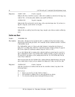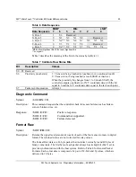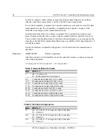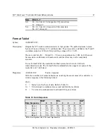
3M™ MicroTouch™ Controller EX Serial Reference Guide
23
3M Touch Systems, Inc. Proprietary Information -- 29087v03
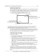
Determining Target Areas
The default calibration targets (points) are located 12.5% (1/8) inward from the corners of
the video image. For example, suppose the display resolution of your display is 1024 x
768. The Calibrate Extended command calculates the amount to move inward as follows:
Amount to move inward in the X direction: 1024 x 1/8 = 128
Amount to move inward in the Y direction: 768 x 1/8 = 96
*
The coordinates are in
video
terms, with the origin (0, 0) in the upper left corner of the sensor. Examples from the
controller’s
perspective, however, place the origin at the lower left corner of the sensor (numbers in brackets). The
controller outputs 0 to 64K on both axes independent of display screen resolution.
The Calibrate Extended command then positions the first calibration target inward from
the lower left corner and the second calibration target inward from the upper right corner.
The following illustration shows how the calibration targets are calculated.
Calibrate Extended Procedure
To use the CX command:
1.
Enter the Calibrate Extended (CX) command. The controller sends an initial
acknowledgment of <SOH>0<CR>.
2.
Touch the sensor at a lower left target, which is located 12.5% (1/8) in from the
corner of the video image. The controller returns an acknowledgment of
<SOH>1<CR>. This is a positive response. If you receive a negative response
<SOH>0<CR>, you can cancel the calibration by issuing a Reset command and then
start over again.
3.
Touch the sensor at an upper right target, which is located 12.5% (1/8) in from the
corner of the video image. The controller returns an acknowledgment of
<SOH>1<CR>. This is a positive response. If you receive a negative response, you
must start over again.
Touching the two valid calibration points results in a successful calibration. If either
calibration point is invalid, the calibration fails. The EX122 and EX112 controllers
restore the previous calibration values. If the Calibrate Extended failed, repeat the CX
process.
(0, 767) [0, 1024]*
[1024, 1024]*
Upper Right Calibration Target
X = 1023 – (1024 x 1/8) = 1023 – 128 = 895
Y = 0 + (768 x 1/8) = 0 + 96 = 96
Lower Left Calibration Target
X = 0 + (1024 x 1/8) = 0 + 128 = 128
Y = 767 - (768 x 1/8) = 767 - 96 = 671
(0, 0) [0, 0]*
(
1023, 0) [1024, 0]*
(128, 671)
(895, 96)


