background image

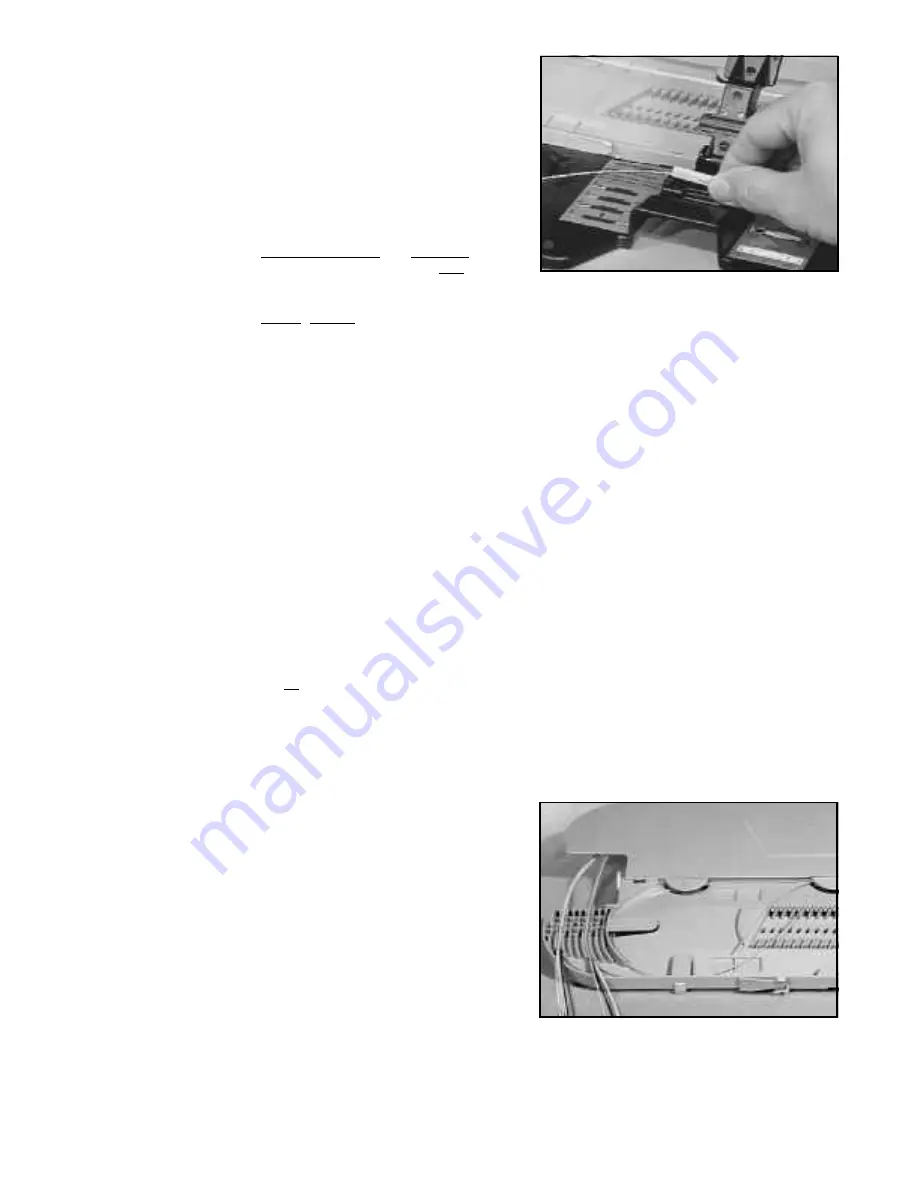
4.09 Remove the Fibrlok Splice from the Assembly Tool by first

removing the fibers from the foam retention pads and then
lifting the splice from the splice holding cradle.

Note:

Do not attempt to “tune” or optimize the splice as
this may result in higher splice loss.   Fibrlok splices
optimize fiber alignment within the metal element
inside the splice when properly installed per the
previous instructions.

If fiber bows are NOT observed as described, repeat
steps 4.02 - 4.07 of Splice Assembly but DO NOT
fully remove  fibers from splice.  If bows are still not
observed, remove fibers, strip, and recleave
checking for proper cleave length.  Resplice per
splicing procedure using_a_new splice.

In the event a splice must be refabricated, simply cut
the fibers at each end of the splice (this will remove 1
1/2" of fiber from the loop) and resplice per
instructions.  Splice refabrication will require a
length of 2 inches on each fiber.

DO NOT REUSE FIBRLOK SPLICES.

5.0 Fiber Organization and Splice Storage

When storing fiber slack in a splice tray, the spliced fiber
ends will twist one full turn for each full loop of fiber being
stored.  This rotation places stress on the fibers.  This
rotational stress makes fiber organization more difficult and
may affect fiber/splice performance, particularly in 900 µm
coated fibers.  The stiffness of the 900 µm  fiber does not
distribute this stress in the same manner as 250 µm coated
fiber.  The following procedure is strongly recommended
when splicing 900 µm coated fibers and will improve fiber
organization when splicing all fiber types.

5.01 Secure the buffer tubes of the fibers to be spliced to the tray

so that the fibers are free to rotate through the point of
attachment.

5.02 Select the first two fibers to be spliced and lay them into the

tray.  Trim the fibers so they are the right length for splicing
plus approximately 1 to 2 inches (2.5 to 5 cm) for fiber end
preparation.

Содержание Fibrlok 2500

Страница 1: ...Instructions Issue 6 August 1991 Fibrlok Optical Fiber Splicing System TM ...

Страница 2: ...g 250 µm and 900 µm diameter plastic coated fiber 1 01 Fibrlok Optical Fiber Splice Jacket Cap Fiber Entry Port each end Fiber Size Designation Circles 1 4 circle for 250 µm coating full circle for 900 µm coated fiber End Plug each end The Fibrlok 2599 Splice is for splicing 900 µm fiber to 900 µm fiber The Fibrlok 2590 Splice is for splicing 250 µm fiber to 900 µm fiber The Fibrlok 2525 Splice is...

Страница 3: ...rm Splice Holding Cradle Finger Cutout Base Fiber Cleave Length Gauge both ends of tool Pivoted Handle shown open Toggle Arm Fiber Retention Pad Fiber Alignment Guides 2 Fiber Retention Pad Instruction Label 2 Mounting Holes 4 1 03 Tools and Materials Required FibrlokTM 2500 or 2501 Assembly Tool Plastic Coating Buffer Stripper Reagent Grade Isopropyl Alcohol Lint Free Wipes Cleaver Fibrlok 2505 A...

Страница 4: ...zation and splice storage 2 04 Remove Fibrlok splice from protective package Load the splice into the assembly tool by pressing firmly at the ends of the splice Note Carefully follow health and safety information on Fibrlok Splice label or Material Safety Data Sheet 2 05 If using the Fibrlok 2501 Assembly Tool rotate the toggle arms for the appropriate fiber size Inward 250 µm Outward 900 µm Note ...

Страница 5: ...eave Length for End of Splice with Black Plug Symbol Fibrlok Splice Designation 3M Fibrlok 2525 250 µm x 250 µm 3M Fibrlok 2590 250 µm x 900 µm 3M Fibrlok 2599 900 µm x 900 µm 14 0 mm 0 5 mm 551 in 020 in 14 0 mm 0 5 mm 551 in 020 in 12 5 mm 0 5 mm 492 in 020 in Note The cleaver should be in good operating condition and used in accordance with the manufacturer s instructions A cleaver that produce...

Страница 6: ...into the splice immediately following cleaning and placing in retention pad to minimize exposure to the atmosphere and reduce the risk of contamination Note Push fiber straight into fiber alignment guide Not at an angle 4 03 Gently continue pushing the fiber into the splice until resistance is felt When fully inserted the first fiber should be straight or have a slight bow up to 1 inch 3 mm Note I...

Страница 7: ...an it had initially 4 07 Push the first fiber back against the second fiber until there are equal bows in both fibers Note Do not pull on either of the fibers following establishment of the bows in the first and second fibers The fiber ends must be held together by the compressive forces induced by the bows to produce a low loss splice 4 08 Pivot the handle of the Fibrlok Assembly Tool down until ...

Страница 8: ...lice refabrication will require a length of 2 inches on each fiber DO NOT REUSE FIBRLOK SPLICES 5 0 Fiber Organization and Splice Storage When storing fiber slack in a splice tray the spliced fiber ends will twist one full turn for each full loop of fiber being stored This rotation places stress on the fibers This rotational stress makes fiber organization more difficult and may affect fiber splic...

Страница 9: ...plice holder or tray whenever possible 5 04 Remove the minimum amount of fiber required for fiber preparation and splicing Remove less than one loop if possible 5 05 Prepare fibers and complete splice as desribed in Section 3 and 4 5 06 Carefully lay the splice on top of the holder without securing the splice into the holder ...

Страница 10: ...s conventional camera type tripods and other standard telco splicing rig components The 2505 Mounting Adapter provides the ability to mount the Fibrlok Assembly Tool on a variety of surfaces and in any orientation for splicing in difficult locations such as manholes aerial splice points pedestals and distribution frames 6 0 Splicing Accessories 6 01 The 3M FibrlokTM 2524 Splice Organizer Tray hold...

Страница 11: ...h 100 pkg Magnifier Cleaved Fiber Inspection Coaxial Cable Stripper Instruction Manual 6 03 3M Fiber Preparation Kits provide all the tools necessary for the assembly of the Fibrlok Splice Fiber Splice Preparation Kits are available in a variety of combinations with or without the Fibrlok Assembly Tool and or the cleaving tool for those who may already own these splicing tools 3M Stock Number 80 6...

Страница 12: ... the Seller which are not contained in the Seller s current publications shall have no force or effect unless contained in an agreement signed by an authorized officer of the Seller The statements contained herein are made in lieu of all warranties express or implied including but not limited to the implied warranties of merchantability and fitness for a particular purpose which warranties are her...

Отзывы: