3M DBI SALA 8518581 Скачать руководство пользователя страница 9

9

provided by DBI-SALA must meet the geometric requirements 

shown in Figure 4. Position the support structure so the load and 

the lifeline of the winch can be directed over the work area when 

installed. For personnel use, do not position the support structure 

where the worker will have to swing under the support structure 

to reach the work area. Avoid positioning the support structure 

where the working line may abrade against sharp edges.

 IMPORTANT: 

Position the winch and support structure in a location 

which allows the operator to safely use the winch.
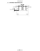
C. MOUNTING PLATE: 

The Digital Winch is equipped with 

a universal mounting plate. The universal mounting plate 

is designed to attach to the quick mount bracket and the 

advanced series winch mount bracket (see Figure 5) and will 

accommodate most other support structures which meet the 

requirements specified in section 3.3. See the support system 

user manual for mounting information or contact DBI-SALA 

for optional mounting kits. When attaching the winch to the 

support, one of the attachment features (i.e., bolt or stud) 

must capture the structural carrying handle.

D. WELDED INSTALLATIONS: 

If welding the mounting bracket 

to a support structure it is recommended that the welding be 

done by a certified welder. Portions of the mounting bracket 

that have been exposed due to welding should be painted or 

otherwise protected from corrosion.

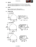
Figure 4 - Required Load Strength

1,900 ft-lbs

moment load

36 in. Min

Recommended

Directional 

Sheave

2,500 lbs.

in direction of pull

Left Hand Retrieve

(cable feeds off top)

Right Hand Retrieve

(cable feeds off bottom)

Wire rope 

directional sheaves 

must have a 

minimum tread 

diameter of 2.5 in.

625 ft-lbs

moment load

2,500 lbs.

in direction of pull

netzerotools.com

netzerotools.com

Содержание DBI SALA 8518581

Страница 1: ...must be followed for proper use and maintenance of this product Alterations or misuse of this product or failure to follow instructions may result in serious injury or death IMPORTANT If you have ques...

Страница 2: ...Optional Removable Crank Arm Optional Permanent Crank Arm Carrying Handle Universal Mounting Plate Winch Secondary Drive Hub 9 1 retrieval ratio Primary Drive Hub 4 1 retrieval ratio Power Drive Clut...

Страница 3: ...be independently evaluated and classified for use as a single point suspension system See OSHA regulation 29 CFR 1926 451 and 29 CFR 1910 28 B PERSONNEL RIDING The Digital Winch is used to raise or lo...

Страница 4: ...EST SYSTEMS Personal fall arrest systems used with the Digital Winch must meet applicable state and federal regulations and the requirements stated in section 3 3 D PHYSICAL AND ENVIRONMENTAL HAZARDS...

Страница 5: ...nintentionally disengage see Figure 2 Connectors must be compatible in size shape and strength Self locking snap hooks and carabiners are required by ANSI Z359 1 and OSHA 2 3 MAKING CONNECTIONS Only u...

Страница 6: ...ebar or cross members that are not shaped in a way that can capture the gate of the hook C In a false engagement where features that protrude from the snap hook or carabiner catch on the anchor and wi...

Страница 7: ...factors that affect your safety during use Some important points to consider when planning your system are A HAZARD EVALUATION Evaluate job site hazards prior to starting work Consult applicable OSHA...

Страница 8: ...the anchorage strengths set forth in A and B must be multiplied by the number of PFAS attached to the anchorage Per OSHA 1926 500 and 1910 66 Anchorages used for attachment of a PFAS shall be independ...

Страница 9: ...ccommodate most other support structures which meet the requirements specified in section 3 3 See the support system user manual for mounting information or contact DBI SALA for optional mounting kits...

Страница 10: ...lications requiring a secondary PFAS the winch line should be connected to a Y type lanyard and this lanyard Figure 6 Connecting to Winch Line Figure 5 Mounting Bracket DBI SALA Quick Mount Bracket Un...

Страница 11: ...he drum Route the line over the support structure pulley system Refer to the support structure user instructions for cable routing TO RAISE A LOAD Rotate the winch crank handle in the raise direction...

Страница 12: ...grity of the attachment and support system as follows A Crank the winch handle in the raise direction until the line is snug The worker should slowly transfer their weight to the harness and lifeline...

Страница 13: ...feline 3 9 RETRIEVING A WORKER Communicate with the worker when preparing to retrieve them and maintain communication throughout the procedure Place the crank handle in the 4 1 or 9 1 drive hub as app...

Страница 14: ...cable will feed off the top of the drum in this configuration changing the moment load requirements as specified in Figure 4 4 0 TRAINING 4 1 It is the responsibility of the user to assure they are fa...

Страница 15: ...The handle must not be bent or distorted and must rotate freely The locking pin must lock and hold the handle perpendicular to the arm Removable crank arm if present must lock positively into each of...

Страница 16: ...body support connectors etc according to manufacturer s instructions 5 3 LIFELINE INSPECTION WIRE ROPE Inspect entire length of wire rope assembly starting at the hook Always wear protective gloves w...

Страница 17: ...The line must be free of chemical or heat damage indicated by brown discolored or brittle areas C The line must be free of ultraviolet damage indicated by discoloration and the presence of splinters a...

Страница 18: ...A 6 4 Store this equipment in a cool dry clean environment out of direct sunlight Avoid areas where chemical vapors exist Inspect after any period of extended storage 6 5 Clean and store body support...

Страница 19: ...anced Digital Winch 27 lbs 12 2 kg plus lifeline 300 Series Advanced Digital Winch 27 5 lbs 12 4 kg plus lifeline 7 3 LOADS Maximum Working Load 450 lbs 204 kg Winch Mechanism Proof Load 5000 lbs 22 2...

Страница 20: ...20 406 10 3 mm 2 06 52 3 mm 75 19 mm 2 06 52 3 mm D UNIVERSAL MOUNTING PLATE netzerotools com netzerotools com...

Страница 21: ...esent and fully legible For ordering purposes the part number is listed near the lower right hand corner of each label B A C A B 5 TO 8 USES WD 40 9504598 REV C C 9504600 REV F Advanced Systems Digita...

Страница 22: ..._______ DATE PURCHASED ______________DATE FIRST USED __________ INSPECTION DATE INSPECTION ITEMS NOTED CORRECTIVE ACTION MAINTENANCE PERFORMED Approved By Approved By Approved By Approved By Approved...

Страница 23: ...582 8518583 8518584 8518585 8518586 8518587 8518588 8518589 8518590 8518591 8518592 8518601 8518602 8518603 8518604 8518605 8518606 8518607 8518608 8518609 8518610 8518611 8518612 8518613 8518614 8518...

Страница 24: ...itional warranties or in any way increase the scope of this warranty CAPITAL SAFETY will not accept liability for defects that are the result of product abuse misuse alteration or modification or for...

Отзывы: