3M CFS101BWF Скачать руководство пользователя страница 8

Installation Site Selection:

Select the location of your backwash system with care. Various conditions which contribute to proper location are as follows:


1)   Locate as close as possible to water supply source.


2)   Locate as close as possible to a drain.


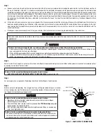
3)   Locate in correct relationship to other water conditioning equipment (Figure 1).


4)   Locate the backwash system in the supply line BEFORE the water heater. Temperatures above 110°F (43.3°C) will damage the backwash system 

and void the factory warranty.


5)   DO NOT install the backwash system in a location where freezing temperatures occur. Freezing may cause permanent damage and will also void 

the factory warranty.


6)   Allow suffi cient space around the installation for easy servicing.


7)   Provide a non-switched 110V, 60Hz (220V, 50Hz for specifi ed systems) power source for the control valve.

 WARNING

To reduce the risk associated with ingestion of contaminants:

• 

Do not 

use with water that is microbiologically unsafe or of unknown quality without adequate disinfection before or after the system.

CAUTION

To reduce the risk associated with property damage due to water leakage:

• 

Protect from freezing

, relieve pressure and drain system when temperatures are expected to drop below 33°F (0.6°C).

• 

Do not

 install on hot water supply lines. The maximum operating water temperature of this fi lter system is 110°F (43.3°C).

• 

Do not 

install systems in areas where ambient temperatures may go above 110°F (43.3°C) or below 40°F (4.4°C).

Facts to Remember While Planning Your Installation:


1)   All installation procedures MUST conform to local and state plumbing codes.


2)   If high water demand devices/activities are to be treated by the backwash system, a larger model MUST be selected to accommodate the higher fl ow 

rate plus the backwashing requirements of the backwash system. Consult your dealer for alternative instructions if the pumping rate is insuffi cient.


3)   Remember that the backwash system INLET is attached to the pipe that supplies water (i.e. runs to the pump) and the OUTLET is the line that runs 

toward the water heater.

CAUTION

To reduce the risk associated with property damage due to plugged water lines:

•  Pay particular attention to correct orientation of control valve. Water fl ow should match arrow on control valve. The Inlet and Outlet of other water treatment 

equipment products will vary depending on the control valve brand used.


4)   Before beginning the installation it is advisable to study the existing piping system and to determine the size, number and type of fi ttings required. 

 WARNING

To reduce the risk associated with a hazardous voltage:

•  If the electrical system requires use of the cold water system as an electrical safety ground, a jumper must be used to ensure a suffi cient ground connection across 

the fi lter installation piping — refer installation to qualifi ed personnel.


5) Sweep the fl oor to eliminate objects that could pierce the media tank.

1-3

Содержание CFS101BWF

Страница 1: ...AND OPERATING INSTRUCTIONS CFS101BWF and CFS201BWF BACKWASH FILTRATION SYSTEMS Installer Please leave this manual with owner operator Owner Operator Please retain for operation and future maintenance...

Страница 2: ......

Страница 3: ...ts Do not use with water that is microbiologically unsafe or of unknown quality without adequate disinfection before or after the system To reduce the risk of physical injury Shut off inlet water supp...

Страница 4: ...ties may deteriorate plastic Take care when using pliers or pipe wrenches to tighten plastic fittings as damage may occur if over tightening occurs Do not install in direct sunlight or outdoors Mount...

Страница 5: ......

Страница 6: ...ulfide H2 S must be tested for at the well site For accuracy the sample must be drawn with the pump RUNNING and the test be completed within ONE minute after the sample is drawn Analysis Of Your Water...

Страница 7: ...re tank will indicate high and low system pressure Record your water pressure data below Water Pressure Low _________psi High _________psi 2 The pumping rate of your well pump must be sufficient for s...

Страница 8: ...Do not install systems in areas where ambient temperatures may go above 110 F 43 3 C or below 40 F 4 4 C Facts to Remember While Planning Your Installation 1 All installation procedures MUST conform...

Страница 9: ...ed water lines Pay particular attention to correct orientation of control valve Water flow should match arrow on control valve The Inlet and Outlet of other water treatment equipment products will var...

Страница 10: ...of filter media may be used in this product depending upon the application During installation dust may cause irritation to skin eyes and respiratory tract and may affect lungs Utilize a NIOSH approve...

Страница 11: ...e 2 4 Open Bypass Valve approximately 1 4 of the way to full open Service Position allowing unit to fill slowly This will purge entrapped air in the bed b Once a steady stream of water is flowing to d...

Страница 12: ...desired backwashing schedule Typically these units are backwashed every third day Consult your dealer for their recommendations for your water How To Manually Backwash Your Filter At Any Time Turn the...

Страница 13: ...l valve Dispose of spent media in accordance with federal state and local regulations a Remove control valve by rotating the valve head assembly to the left or counter clockwise Before loading the med...

Страница 14: ...E position Repair or re place if necessary B Internal valve leak 1 Check piston and spacers and seals Replace as neces sary C Distributor not properly seated in control valve 1 Make sure distributor i...

Страница 15: ...17 43 2 18 45 7 Height 50 127 58 147 32 Approximate Shipping Weight lbs kg l media 45 20 57 26 Maximum operating temperature 110 F 43 3 C Electrical requirements 110V 60Hz Operating pressure 20 125 p...

Страница 16: ...ravel Underbed 68696 37 68686 38 NOTE When ordering components always specify model number 5 6 4 3 2 1 Media Options Model Part Description Application Cu Ft Provided A Media A 050P Activated Carbon R...

Страница 17: ...5 3 BACKWASH CONTROL...

Страница 18: ...8706X 1 NPT Bypass Valve Assy incl Ref Items 49 58 60049 18706 10X 1 BSP Bypass Valve Assy incl Ref Items 49 58 26 19170 Motor 110V 60 Hz 18825 Motor 220V 50Hz 27 11384 Motor Mtg Ground Screw 29 19171...

Страница 19: ......

Страница 20: ...cation Inc s exclusive obligation Warranty Period One 1 year on the entire product unit Five 5 years on the media tank only does not include internal component parts Five 5 years on the control valve...

Отзывы: