3DGence DOUBLE P255 - maintenance activities | version 07.2021
Prepared models .stl and .gcode are also available at
(the tab is available after creating an account and registering the device).
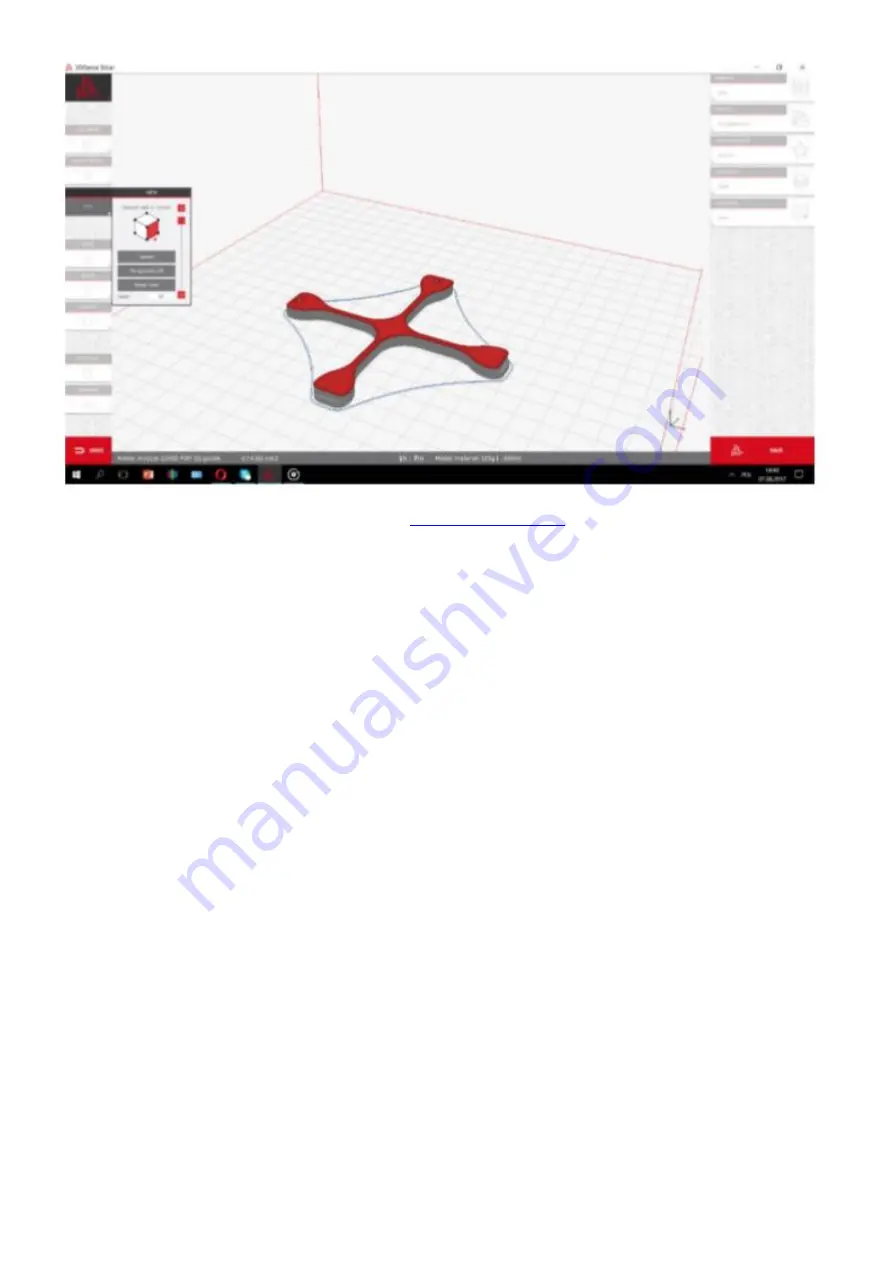
After printing, cooling down and removing the calibration cross carefully from the heatbed, measure the cross along
X and Y axes. They are marked on the model. Different tools can be used to make the measurement, but their
accuracy must be at least 0.05 mm:
• slide caliper,
• micrometer,
• coordinate measuring machine,
• optical tools.
The printout should be measured along X and Y axes. To increase the measurement certainty, follow the below
instructions:
• the measuring point should be in the middle of the model height above the step, both points at the height of the
same layer (fig. 59),
• measurements for X and Y axes should be mad
e 5 times for each axis. Reject the highest and the lowest
measurement result from each group. Other measurements should be averaged for each axis (fig. 60).


