9
3D SYSTEMS, INC
.
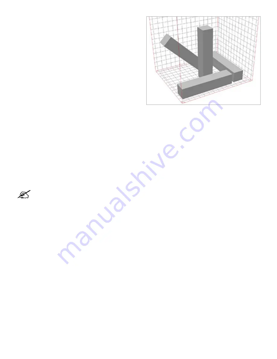
Cross-sections on a layer
Pay attention to the total cross-sectional area of the parts on
a layer. If there are multiple parts that contain heavy cross-
sections, make sure the parts are located so that the large cross-
sections happen on different layers. This will reduce the chance
of short feeds.
Although the process parameter default values in the Standard mode are optimized by 3D Systems, slight adjustments may be
needed to further optimize the process for specific powder blends and applications.
Part and Scale parameters - set for each individual part. Part parameters include
laser power
and
scale
for shrinkage.
The profile editors in the Build Prep software and in Sinter are used to adjust parameter values. You create a row in the table for
the initial value and for each Z height when the parameter should change. If you intend for a parameter to use the same value
throughout a build, its table should have only one row, with a Z height of 0.000 and the desired value. Profile Editors will show
Min, Max, and default values for parameter values.
Build set points,
Parameter values
- set independently for each stage by specifying a stage z value with an associated
parameter value. Build parameters include
part heater set point
and
feed dose amount
, etc.
Due to the material blend or application specific needs, it may be necessary to increase or decrease the part bed set point.
•
If part cake at breakout is too soft overall, then increase the part heater set points by small increments (0.5 to 1.0
degrees)
•
If part cake at breakout is too hard overall, then decrease the part heater set point by small increments (0.5 to 1.0
degrees)
This value is the rotation of the Feed Roller (located in the feed hopper). It controls the amount of the feed dose.
•
The default values should release enough powder from the feed hopper so that when the traverse roller moves across the
part bed, there is sufficient powder to cover the entire build area and deposit a small amount in the powder-return piston.
Observe the feed dose when preparing the printer for a print job.
◊
During the warmup and cooldown stage, a smaller feed dose is adequate.
◊
During build stage (during scanning), a larger feed dose is required to completely cover the scanned area.
•
If the powder dose is too small, there is a possibility of short feeds. See
Short Feeds
in the glossary.
•
If the powder dose is too large, the powder dose may not properly heat, and large amounts of powder will be pushed past
the return piston.
•
Increase or decrease the Feed Powder amount in small increments of 0.01.
•
If scanned area is very similar on each layer, the same feed amount can be used for entire build stage. If scanned area
varies significantly from layer to layer, then use an amount that will work for the layers with the larger area, or profile the
feed amount.
•
If the printer is not run for several days, it may take several layers while leveling powder for feed powder to dispense
properly.
•
If Feed Hopper is emptied completely and then re-filled, allow at least two hours before starting a build so that powder
settles and feeds correctly.
Print Process Settings
Part Bed Heater Set Point
Feed Powder Amount
Note: On SLS 380, the IR camera balances the individual heater output during the build to maintain an even
temperature across the build area so there is no need to adjust individual heater output.


