background image

Monitoring Trunks and B-channels using Web Interface

39

Monitoring Trunks 
and B-channels 
using Web Interface

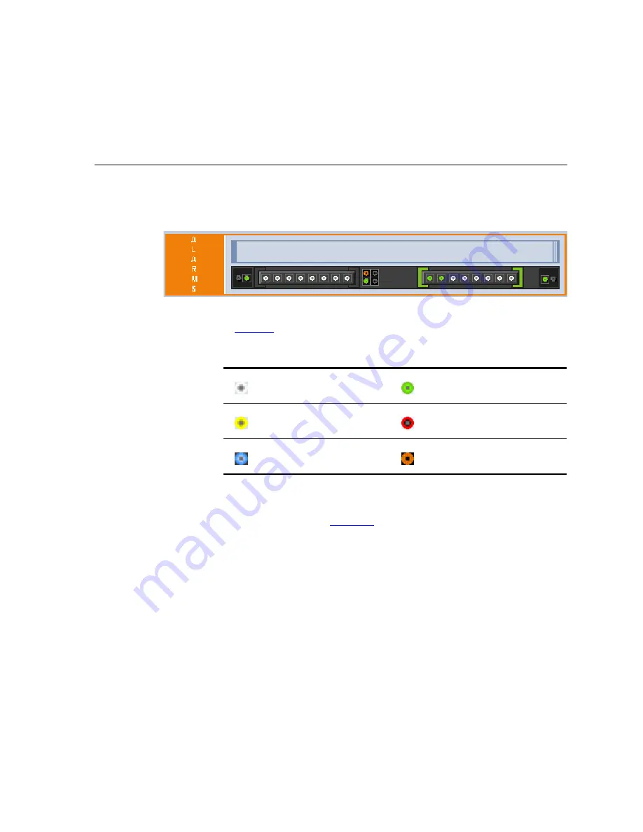
To monitor the status of the trunks and B-channels, open the 

Home

 page 

by clicking the 

Home

 icon.

Figure 13   

Home Page

The color-coding of the Trunk status icons in the Home page is described 
in 

Table 12

:

To monitor the details of a Trunk's B-channel, perform these steps:

1

Open the 

Trunk & Channel Status

 screen (

Status & Diagnostics > 

Channel Status

). See 

Figure 14

.

Table 12   

Colors of Trunk Status Icons 

(White) — Disabled

(Green) — Active

(Yellow) — RAI alarm

(Red) — LOS / LOF alarm

(Blue) — AIS alarm

(Orange) — D-channel alarm

Содержание VCX V7122

Страница 1: ...http www 3com com Part Number 900 0506 01 Rev AA Published February 2008 3Com VCX V7122 Digital Gateway Installation Guide System Release 5 2 ...

Страница 2: ...documentation and the software described herein are provided to you subject to the following United States Government Legend All technical data and computer software is commercial in nature and developed solely at private expense Software is delivered as Commercial Computer Software as defined in DFARS 252 227 7014 June 1995 or as a commercial item as defined in FAR 2 101 a and as such is provided...

Страница 3: ...nting the V7122 13 Desktop Mounting 13 19 inch Rack Mounting 13 Cabling the V7122 15 Connecting the E1 T1 Trunk Interfaces 16 Installing the Ethernet Connection 18 Connecting the Power Supply 18 CONFIGURING THE V7122 MEDIA GATEWAYS Assigning the V7122 IP Address 21 Assigning an IP Address Using HTTP 22 Assigning an IP Address Using the CLI 23 Restoring Networking Parameters to their Initial State ...

Страница 4: ... AND BACKING UP THE V7122 MEDIA GATEWAY CONFIGURATION MONITORING THE V7122 MEDIA GATEWAYS Monitoring the V7122 Chassis LEDs 37 TP 1610 Front Panel LED Indicators 37 Monitoring Trunks and B channels using Web Interface 39 UPGRADING THE V7122 MEDIA GATEWAYS Software Upgrade Wizard 41 Updating the Auxiliary Files 47 REGULATORY INFORMATION OBTAINING SUPPORT FOR YOUR 3COM PRODUCT Customer Support 57 ...

Страница 5: ...ers at www 3Com com under Support Downloads Drivers When viewing this manual electronically all cross references are hyperlinked Click the link blue and underlined to navigate to the target location To return to your original location simultaneously press the ALT key and the Left Arrow key How to Use This Guide This book covers these topics Chapter 1 Quick Start Chapter 2 Installing the V7122 Medi...

Страница 6: ... register your product and get support from 3Com Notices WEEE EU Directive Pursuant to the WEEE EU Directive electronic and electrical waste must not be disposed of with unsorted waste Please contact your local recycling authority for disposal of this product Abbreviations and Terminology Each abbreviation unless widely used is spelled out in full when first used Only industry standard terms are u...

Страница 7: ...P gateway interfaces between the CO PBX line and the Internet FXS Foreign Exchange Station is the interface replacing the Exchange that is the CO or the PBX and connects to analog telephones dial up modems and fax machines The FXS is designed to supply line voltage and ringing current to these telephone devices An FXS VoIP gateway interfaces between the analog telephone devices and the Internet WA...

Страница 8: ...8 ABOUT THIS GUIDE ...

Страница 9: ...the first time Prior knowledge of IP networks is recommended The following steps provide a quick setup flow 1 Unpack the V7122 Gateways 2 Mount the V7122 Gateways 3 Cable the V7122 Gateways 4 Assign the V7122 Gateway IP Addresses 5 Configure the V7122 Gateways basic control protocol parameters 6 Configure the PSTN parameters ...

Страница 10: ...10 CHAPTER 1 QUICK START ...

Страница 11: ...ersonnel The figure below shows the front panel of the V7122 media gateway For information on the V7122 LEDs see Monitoring the V7122 Chassis LEDs Figure 1 V7122 Front View Table 2 V7122 Front View Component Descriptions Item Label Component Description 1 FAULT Dual AC Power LED 2 cPCI board locking screws 3 cPCI latches 4 TP 1610 cPCI board 16 trunk configuration 5 Status LED indicators 6 T1 E1 S...

Страница 12: ...ce you have completed these hardware installation steps you can begin configuring the gateway see Configuring the V7122 Media Gateways Unpacking Follow the procedure below for unpacking the box in which the V7122 is delivered To unpack the V7122 perform these steps 1 Open the carton and remove packing materials 2 Remove the V7122 unit from the carton 3 Check that there is no equipment damage 4 Che...

Страница 13: ...igure 2 Two brackets and four bracket to device screws for 19 inch rack installation option Four anti slide bumpers for desktop mounting This Installation Guide Figure 2 19 inch Rack Desktop Accessories Mounting the V7122 The V7122 can be mounted on a desktop or installed in a standard 19 inch rack Desktop Mounting Optionally attach the four supplied anti slide bumpers to the base of the V7122 and...

Страница 14: ...dition is not achieved due to uneven mechanical loading Circuit Overloading Consideration should be given to the connection of the equipment to the supply circuit and the effect that overloading of the circuits might have on overcurrent protection and supply wiring Appropriate consideration of equipment nameplate ratings should be used when addressing this concern Reliable Earthing Reliable earthi...

Страница 15: ...ar brackets note the following The distance between the screws on each bracket is 26 5 mm To attach the brackets use 4 40 screws with a maximal box penetration length of 3 5 mm To install the V7122 on a 19 inch rack shelf perform these steps 1 Place the gateway on the pre installed shelf 2 You re now recommended to perform the optional steps of fastening the device to the frame of the rack as desc...

Страница 16: ...es see Connecting the E1 T1 Trunk Interfaces 3 Install the Ethernet connection see Installing the Ethernet Connection 4 Connect the power supply see Connecting the Power Supply Connecting the E1 T1 Trunk Interfaces Connect the V7122 E1 T1 Trunk interfaces using either Telco V7122 with 16 spans or RJ 48 V7122 with 1 2 4 or 8 spans connectors as described in the procedure below Table 3 V7122 16 Trun...

Страница 17: ...according to the pinouts described in Table 4 and to mate with the female connector illustrated in the figure below Figure 5 50 pin Female Telco Board Mounted Connector To connect E1 T1 trunk interface using RJ 48c connectors perform these steps 1 Connect the E1 T1 trunk cables to the ports labeled Trunks 1 to 8 in the case of the 8 trunk device on the V7122 RTM 2 Connect the other ends of the Tru...

Страница 18: ...ee Assigning an IP Address Using HTTP you may be required to disconnect this cable and re cable it differently Figure 7 Pinout of RJ 45 Connectors For redundancy it s recommended to connect each of the Ethernet connectors to a different switch Connecting the Power Supply Connect the V7122 to the power supply using one of the following methods Connecting AC Power Supply To connect power when using ...

Страница 19: ...he LED on the left side of the chassis is only connected when the dual AC is used It is not relevant to the single AC power connection If only a single socket is connected to the AC power while the other plug is left unconnected the chassis LED on the left side is lit red indicating that one of the dual power inlets is disconnected When both the AC power cables are connected one of the plugs can b...

Страница 20: ...20 CHAPTER 2 INSTALLING THE V7122 MEDIA GATEWAYS ...

Страница 21: ...ays are fully independent each gateway having its own MAC and IP addresses To assign an IP address to each of the V7122 modules use one of the following methods HTTP using a Web browser see Assigning an IP Address Using HTTP The embedded Command Line Interface CLI accessed using Telnet see Assigning an IP Address Using the CLI Table 5 lists the default IP addresses of the V7122 You can use the Res...

Страница 22: ...t Help 3 Access the V7122 first module s Embedded Web Server see Accessing the Embedded Web Server 4 In the Quick Setup screen Quick Setup menu set the V7122 IP Address Subnet Mask and Default Gateway IP Address fields under IP Configuration to correspond with your network IP settings 5 Click the Reset button and then at the prompt click OK the V7122 applies the changes and restarts This takes app...

Страница 23: ... Yes and then click the Reset button the V7122 is shut down and re activated A message about the waiting period is displayed The screen is refreshed 2 Use a standard Telnet application to connect to the V7122 Embedded Telnet Server 3 Login using the username Admin and password Admin 4 At the prompt type conf and then press Enter the configuration folder is accessed 5 To check the current network p...

Страница 24: ...gateway is powered up After approximately 45 seconds the ACT LED blinks for about four seconds 3 While the ACT LED is blinking press shortly on the reset button located on the front panel the gateway resets a second time and is restored with factory default parameters username Admin password Admin 4 Reconnect the network cable 5 Assign the V7122 an IP address see Assigning the V7122 IP Address 6 L...

Страница 25: ...d Web Server s Quick Setup screen When you have completed the configuration you are then ready to start using the V7122 Once the gateway is configured correctly back up your settings by saving the gateway configuration ini file in a directory on your PC This saved file can be used to restore configuration settings at a future time For information on backing up and restoring the gateway s configura...

Страница 26: ... router Web management Enter this public IP address in the NAT IP Address field Enable the DMZ configuration on the residential router for the LAN port where the V7122 gateway is connected This enables unknown packets to be routed to the DMZ port 3 Under SIP Parameters enter the V7122 domain name in the field Gateway Name If the field is not specified the V7122 IP address is used instead default 4...

Страница 27: ...r matches the prefix defined in the Destination Phone Prefix field and whose source number matches the prefix defined in the adjacent Source Phone Prefix field is sent to the IP address entered in the IP Address field b Click the Submit button the Tel to IP Routing table is automatically updated c Click Quick Setup you re returned to the Quick Setup screen 9 Enable E1 T1 B channels by completing t...

Страница 28: ...unk Settings To configure the trunk settings perform these steps 1 Access the Embedded Web Server see Accessing the Embedded Web Server 2 Open the Trunk Settings screen Advanced Configuration menu Trunk Settings the screen appears with the parameter fields grayed indicating read only and the Stop Trunk button is displayed at the bottom of the screen indicating that the trunk is currently active Th...

Страница 29: ...are stopped the Apply to all Trunks button also appears The parameters are no longer grayed and can now be modified If the trunk can t be stopped because it provides the gateway s clock assuming the V7122 is synchronized with the E1 T1 clock assign a different E1 T1 trunk to provide the gateway s clock or enable TDM Bus PSTN Auto Clock on the TDM Bus Settings screen To assign a different E1 T1 tru...

Страница 30: ...ro substitution for T1 trunks only HDB3 high density bipolar 3 for E1 trunks only or AMI alternate mark inversion used for both T1 and E1 9 From the ISDN Termination Side drop down list applicable only to ISDN protocols select User Side when the PSTN or PBX side is configured as Network side and vice versa If you don t know the V7122 ISDN termination side choose User Side and then open the Channel...

Страница 31: ...ration TDM Bus Settings From the PCM Law Select drop down list select Alaw for E1 trunks and MuLaw for T1 trunks 13 To save the changes so they are available after a power fail perform the following a Click the Maintenance button on the main menu bar the Maintenance Actions screen appears b From the Burn to FLASH drop down list select Yes and then click the Reset button a confirmation message appe...

Страница 32: ...32 CHAPTER 3 CONFIGURING THE V7122 MEDIA GATEWAYS ...

Страница 33: ... and secondary It is recommended that you change the default username and password of the account you use to access the Embedded Web Server To change the username and password perform these steps 1 Open the Web User Accounts screen Advanced Configuration menu Security Settings Web User Accounts option the Web User Accounts screen is displayed See Figure 11 ...

Страница 34: ...nter Network Password screen Note that the username can be a maximum of 19 case sensitive characters 3 To change the password of an account perform these steps a In the Current Password field enter the current password b In the New Password and Confirm Password fields enter the new password Note that the password can be a maximum of 19 case sensitive characters c Click the button Change Password t...

Страница 35: ...ion if you want to protect your VoIP gateway configuration The backup ini file includes only those parameters that were modified and contain other than default values Restore your configuration if the VoIP gateway has been replaced or has lost its configuration You can restore the VoIP gateway configuration from a previous backup or from a newly created ini file To restore the VoIP gateway configu...

Страница 36: ... 5 Click the Save button the VoIP gateway copies the ini file to the folder you selected To restore the ini file perform these steps 1 Open the Configuration File screen Advanced Configuration menu Configuration File the Configuration File screen appears 2 Click the Browse button 3 Navigate to the folder that contains the ini file you want to load 4 Select the file and then click the Open button t...

Страница 37: ...ctionality of the front panel LEDs for the TP 1610 board is described in the following tables Note that there is a choice of front panels according to the number of channels Table 7 Chassis LEDs Description Location Color Description Right side of front panel Green Power is on Right side of front panel Red At least one of the internal fans has significantly reduced its speed or has stopped i e fan...

Страница 38: ...el Color Description T1 E1 Status 1 to 8 and T1 E1 Status 9 to 16 Green Trunk is synchronized normal operation Bi color LED Red Loss due to any of the following 4 signals LOS Loss of Signal LFA Loss of Frame Alignment AIS Alarm Indication Signal the Blue Alarm RAI Remote Alarm Indication the Yellow Alarm Table 10 Ethernet LEDs Description Label LED Description LINK Green Link all OK ACT Yellow Tra...

Страница 39: ...icon Figure 13 Home Page The color coding of the Trunk status icons in the Home page is described in Table 12 To monitor the details of a Trunk s B channel perform these steps 1 Open the Trunk Channel Status screen Status Diagnostics Channel Status See Figure 14 Table 12 Colors of Trunk Status Icons White Disabled Green Active Yellow RAI alarm Red LOS LOF alarm Blue AIS alarm Orange D channel alar...

Страница 40: ...EDIA GATEWAYS Figure 14 Home Page 2 Click the required B channel icon whose detailed status you want to view the B channel specific Channel Status screen appears 3 Click the submenu links to view a specific B channel s parameter settings ...

Страница 41: ...u to upgrade software cmp file while maintaining the existing configuration Using the wizard obligates you to load a cmp file You can choose to also use the wizard to load the ini and auxiliary files e g Call Progress Tones but this option cannot be pursued without loading the cmp file For the ini and each auxiliary file type you can choose to reload an existing file load a new file or not load a ...

Страница 42: ...reen At this point the process can be canceled with no consequence to the V7122 click the Cancel button If you continue the process by clicking the Start Software Upgrade button the process must be followed through and completed with a V7122 reset at the end If you click the Cancel button in any of the subsequent screens the V7122 is automatically reset with the configuration that was previously b...

Страница 43: ...e Wizard 43 Figure 16 Load a cmp File Screen 4 Click the Browse button navigate to the cmp file and then click Send File the cmp file is loaded to the V7122 and you re notified as to a successful loading see Figure 17 ...

Страница 44: ...iles Click Cancel the V7122 resets utilizing the cmp ini and all other configuration files that were previously stored in flash memory Note that these are NOT the files you loaded in the previous Wizard steps Click Back the Load a cmp File screen is reverted to see Figure 16 Click Next the Load an ini File screen opens see Figure 18 Loading a new ini file or any other auxiliary file listed in the ...

Страница 45: ...g configuration remains checked by default Ignore the Browse button and uncheck the User existing configuration check box no ini file is loaded the V7122 uses its factory preconfigured values You can now choose to either Click Cancel the V7122 resets utilizing the cmp ini and all other configuration files that were previously stored in flash memory Note that these are NOT the files you loaded in t...

Страница 46: ...he Load a coefficient file screen 8 In the Finish screen see Figure 20 the Next button is disabled Complete the upgrade process by clicking Reset or Cancel Click Reset the V7122 burns the newly loaded files to flash memory The Burning files to flash memory screen appears Wait for the burn to finish When it finishes the End Process screen appears displaying the burned configuration files see Figure...

Страница 47: ...rocess Screen 9 Click the End Process button the Home page appears and the full Web application is reactivated Updating the Auxiliary Files The auxiliary files are configuration dat files that are loaded to the gateway in addition to the ini file to enable enhanced gateway ...

Страница 48: ...value These values may not be the same as the values that were configured for the VoIP gateway at the time of manufacture Note After the file has completed loading the VoIP gateway automatically restarts software is loaded from the flash CAS Only applicable for digital interfaces Up to eight different CAS files containing specific CAS protocol definitions These files are provided to support variou...

Страница 49: ...oice Prompts file 6 Repeat steps 2 through 5 for each file you want to load Figure 22 Auxiliary Files Screen e g SIP Gateways To save the loaded auxiliary files e g CPT to flash memory and reset the gateway perform these steps 1 On the main menu bar click the Maintenance button the Maintenance Actions screen appears 2 Saving an auxiliary file to flash memory may disrupt traffic Therefore disable a...

Страница 50: ... traffic exists and the time has not yet expired the gateway locks 3 Under the RESET group select the Yes option from the Burn to FLASH drop down list and then click Reset the auxiliary files are saved into flash and the V7122 Gateway restarts This takes approximately three minutes to complete When the V7122 has finished restarting the Ready and LAN LEDs on the front panel are lit green ...

Страница 51: ...er s Name AudioCodes Ltd Manufacturer s Address 1 Hayarden Street Airport City Lod 70151 Israel Type of Equipment Analog VoIP System Model Numbers MP 11x FXS FXO Mixed Series MP 114 2FXS 2FXO MP 118 4FXS 4FXO MP 11x FXS Series MP 112 2FXS MP 114 4FXS MP 118 8FXS MP 11x FXO Series MP 112 2FXO MP 114 4FXO MP 118 8FXO MP 124 FXS Series MP 124D FXS I the undersigned hereby declare that the equipment s...

Страница 52: ...ries MP 124 ΣΥΜΜΟΡΦΩΝΕΤΑΙ ΠΡΟΣ ΤΙΣ ΟΥΣΙΩΔΕΙΣ ΑΠΑΙΤΗΣΕΙΣ ΚΑΙ ΤΙΣ ΛΟΙΠΕΣ ΣΧΕΤΙΚΕΣ ΔΙΑΤΑΞΕΙΣ ΤΗΣ ΟΔΗΓΙΑΣ 89 336 EEC 73 23 EEC Hungarian Alulírott AudioCodes Ltd nyilatkozom hogy a MP 11x FXS FXO Series MP 124 megfelel a vonatkozó alapvetõ követelményeknek és az 89 336 EEC 73 23 EEC irányelv egyéb elõírásainak Icelandic æki þetta er í samræmi við tilskipun Evrópusambandsins 89 336 EEC 73 23 EEC Italia...

Страница 53: ...in accordance with the instructions may cause harmful interference to radio communications However there is no guarantee that interference will not occur in a particular installation If this equipment does cause harmful interference to radio or television reception which can be determined by turning the equipment off and on the user is encouraged to try to correct the interference by one or more o...

Страница 54: ...ains among other information a product identifier in the format US AC1IT00BMP11X3AC If requested this number must be provided to the telephone company 2 This equipment is designed to be connected to the telephone network using an RJ 11C connector which is Part 68 compliant The service order code SOC is 9 0Y and the Facility interface code FIC is 02LS2 3 The REN is used to determine the number of d...

Страница 55: ...s experienced with this equipment for repair or warranty information please contact AudioCodes Inc 2099 Gateway Place Suite 500 San Jose CA 95110 phone number 1 408 441 1175 If the equipment is causing harm to the telephone network the telephone company may request to disconnect the equipment until the problem is resolved 7 Installation is described in the Product User s manual Connection to Telep...

Страница 56: ...56 CHAPTER 8 REGULATORY INFORMATION ...

Страница 57: ... Customer Support Customer technical support and service are provided by 3Com Distributors Partners and Resellers from whom the product was purchased To obtain Customer Support for products purchased directly from 3Com contact support 3Com com ...

Страница 58: ...58 APPENDIX A OBTAINING SUPPORT FOR YOUR 3COM PRODUCT ...

Отзывы: