3Com NETBuilder II DPE 80 Скачать руководство пользователя страница 9

Installing in the 4- or 8-Slot Chassis

1-3

Installing in the 4- or 
8-Slot Chassis

To install the DPE module into the NETBuilder II 4- or 8-Slot chassis, follow these 
steps. If you own the Extended chassis, refer to the next section.

Although it is not required, 3Com recommends that you turn off the system 
before you install or remove a DPE module. If you do not turn off the system, 
the bridge/router will automatically reset when you install the DPE module.

You will need a small, flatblade screwdriver.
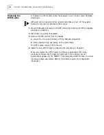
1

Insert the module into the top slot.

Although the figure shows an 8-Slot chassis, the procedure for the 4-Slot 
chassis is exactly the same.

2

Hand-tighten the captive screws, then gently tighten them with a small 
(1/8 in. – 3/16 in.) screwdriver. Do 

not

 overtighten the screws.

A solid connection of the front panel to the chassis is required for proper 
operation. Do 

not

 use the screws to force the board into place.

You are now ready to install the I/O modules. Refer to the appropriate I/O 
module installation guides. After installing your I/O modules, refer to 
“Connecting a PC, Terminal, or Modem”

 on page 1-5

.

c

a

b

d

1

2

3

4

8

7

6

5

®

DPE

PACKET

FORWARD

POWER/

FAULT

RUN

LOAD

TEST

RESET ATTENTION

4

3

2

1

STATUS

CONSOLE

A
B

Grasp left 
and right
sides of 
LED panel.

Make sure module
is right side up.

Push ejector tabs all
the way closed until the 
module is flush with the chassis.

Slide module along 
guide rails until it 
engages the notches
of ejector tabs.

Содержание NETBuilder II DPE 80

Страница 1: ...http www 3com com Installing the NETBuilder II Dual Processor Engine Module For models DPE 40 and DPE 80 Part No 09 0795 000 Published May 1997...

Страница 2: ...Corporation 5400 Bayfront Plaza Santa Clara California 95052 8145 For civilian agencies Restricted Rights Legend Use reproduction or disclosure is subject to restrictions set forth in subparagraph a t...

Страница 3: ...terns 2 2 Replacing the DPE Module 2 4 3 FEATURES AND SPECIFICATIONS Features 3 1 LEDs 3 2 LEDs on the Chassis 3 2 Connectors 3 2 Buttons 3 3 LCD Control Panel 3 3 Physical Specifications 3 3 A UPGRAD...

Страница 4: ...iv...

Страница 5: ...ling and managing the network hardware It assumes a working knowledge of network operations but does not assume prior knowledge of 3Com internetworking equipment If the information in the release note...

Страница 6: ...ercase letters and the appropriate value Commands are not case sensitive Screen displays This typeface represents information as it appears on the screen The words enter and type When you see the word...

Страница 7: ...uilder II EZBuilt system with a preinstalled DPE module go to Connecting a PC Terminal or Modem on page 1 5 The software flash memory card does not ship with the stand alone DPE module and must be pur...

Страница 8: ...chniques when handling the module Use a foot strap and grounded mat or wear a grounded static discharge wrist strap 2 Unpack and inspect the module for shipping damage If you find any damage file a re...

Страница 9: ...exactly the same 2 Hand tighten the captive screws then gently tighten them with a small 1 8 in 3 16 in screwdriver Do not overtighten the screws A solid connection of the front panel to the chassis i...

Страница 10: ...ews then gently tighten them with a small 1 8 in 3 16 in screwdriver Do not overtighten the screws A solid connection of the front panel to the chassis is required for proper operation Do not use the...

Страница 11: ...uts for a 9 pin female to 9 pin female PC cable A null modem type cable may be used Figure 1 2 shows the pinouts for a 9 pin female to 25 pin terminal cable A null modem type cable may be used Figure...

Страница 12: ...Receive Data Request to Send Clear to Send Carrier Detect Signal Ground Data Set Ready Data Terminal Ready Receive Data Transmit Data Carrier Detect Clear to Send Request to Send Signal Ground Data Te...

Страница 13: ...ve The default boot and configuration file paths are to a directory on drive A Refer to the release notes for approved vendors of blank flash memory cards for backup The software guide describes how t...

Страница 14: ...is not accidentally ejected when the eject button is pressed attach the cover as shown Match notches with slots RESET ATTENTION A B Install screw Do not tighten all the way Slide shield toward center...

Страница 15: ...he NETBuilder II system 2 Verify that the power cord is plugged properly into the system s power supply module and into a working outlet 3 Inspect the system s in line power fuse and replace it if nec...

Страница 16: ...Firmware initialization Y G x G Performing non essential board level power on self tests Y G G x G Performing corebus loopback test Y G G x G Performing UART and shared memory test Y G G G x G Valida...

Страница 17: ...G G x YF Serial port or shared memory test failed Return module for repair Y G G G x YF FPROM contents corrupted Return module for repair G G x YF Unable to load bridge router image unable to load fr...

Страница 18: ...isconnect any cables if necessary 3 Remove the DPE module from the chassis a Loosen the two captive screws with the flathead screwdriver b Press outward firmly and evenly on the ejector tabs The DPE m...

Страница 19: ...and 8 MB of shared packet memory provides optimal performance compared with single memory based systems See Appendix A for upgrade instructions DPE 80 64 MB of instruction and data memory and 16 MB o...

Страница 20: ...2 for more information Connectors Table 3 2 describes the module connectors CONSOLE connector Flash memory drives A B STATUS LEDs 1 2 3 4 ATTENTION LED RESET LED Backplane connectors to NETBuilder II...

Страница 21: ...t reset the system to resume operation Physical Specifications The following tables list physical description and electrical and environmental requirements for the DPE module Table 3 3 Physical Descri...

Страница 22: ......

Страница 23: ...tes shipped with this guide for approved memory chip models and vendors You must install SIMMs in pairs of equal sized memory Procedure To upgrade your memory complete the following 1 Locate the memor...

Страница 24: ...SIMM rotate SIMM forward and lift it out of the socket Tab Tab IIIIIIIIIIIIIIIIIIIIIIIIIIII IIIIIIIIIIIIIIIIIIIIIIII IIIIIIIIIIIII IIIIIIIIIIIII IIIIIIIIIIIIIIIIIIIIIIIIIIII IIIIIIIIIIIIIIIIIIIIIIII...

Страница 25: ...Web site 3Com Bulletin Board Service 3ComBBS 3ComFactsSM automated fax service 3ComForum on CompuServe online service World Wide Web Site Access the latest networking information on 3Com Corporation s...

Страница 26: ...day 7 days a week Call 3ComFacts using your Touch Tone telephone using one of these international access numbers Country Data Rate Telephone Number Australia up to 14400 bps 61 2 9955 2073 Brazil up...

Страница 27: ...ces including network planning installation hardware maintenance application training and support services When you contact your network supplier for assistance have the following information ready Di...

Страница 28: ...Netherlands 32 2 725 0202 31 30 6029700 3Com Canada Calgary Montreal Ottawa Toronto Vancouver 403 265 3266 514 683 3266 613 566 7055 416 498 3266 604 434 3266 3Com European HQ 49 89 627320 3Com France...

Страница 29: ...1 1 I installation in NETBuilder II 1 1 installation of NETBuilder II 4 Slot 1 3 8 Slot 1 3 Extended 1 4 L LCD control panel 3 3 LEDs 2 2 2 3 3 2 LOAD LED 2 2 2 3 M MAC address 1 2 main processor 3 1...

Страница 30: ...2 INDEX...

Страница 31: ...ter within the warranty period Products returned to 3Com s Corporate Service Center must be pre authorized by 3Com with a Return Material Authorization RMA number marked on the outside of the package...

Страница 32: ......

Отзывы: